
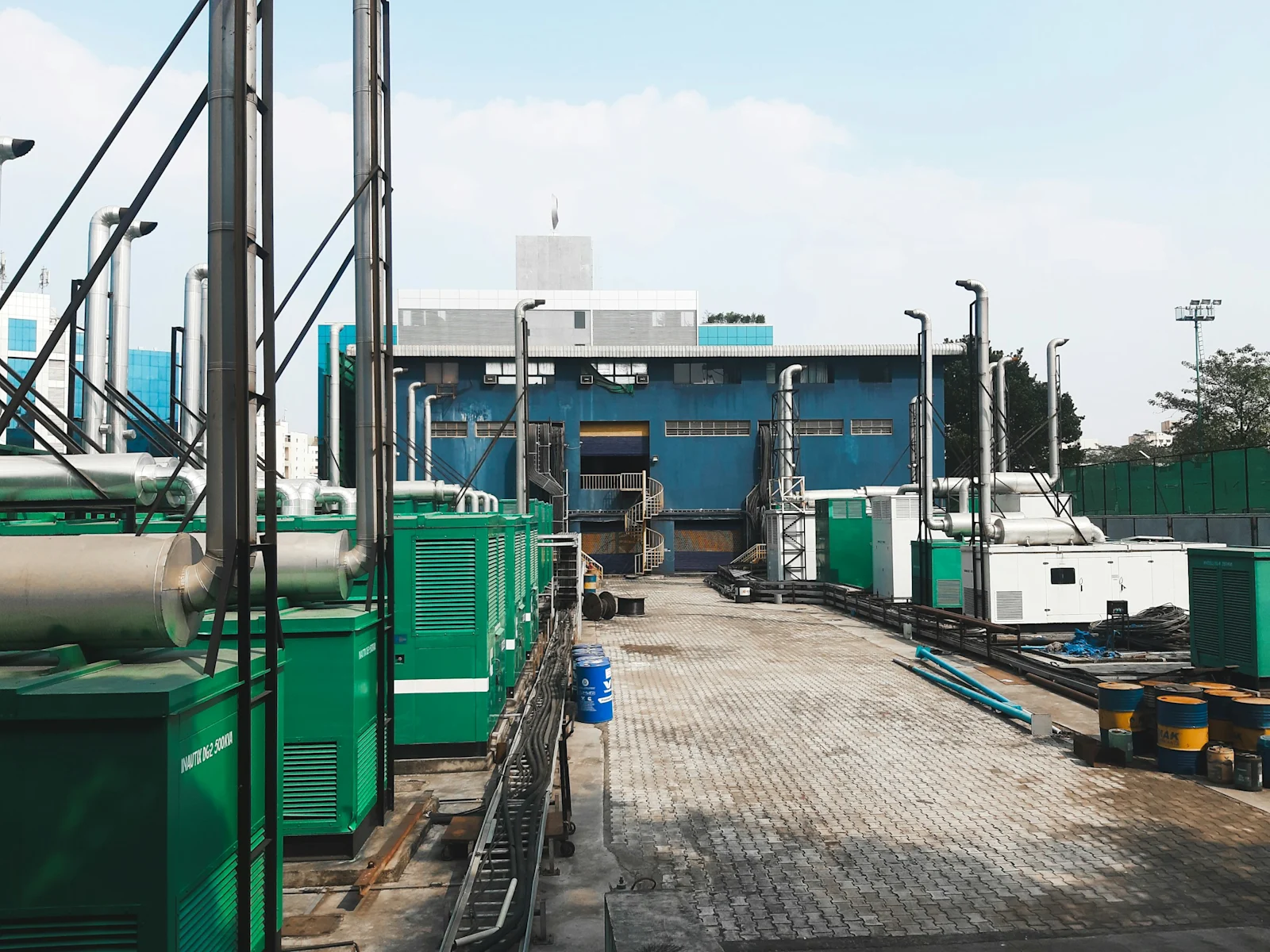
Data Centre Backup Power in India: Generator Sizing, the Emissions Regime and Storage
Backup power for Indian data centres, covering the ride-through hierarchy, generator sizing under Indian derating, the emissions standard that does not apply to data centre sets, gas as an alternative fuel, and where battery storage can and cannot displace
The short answer. Backup power is a small share of Indian data centre capital cost and is idle almost all of the time. Generator plant must be sized against site-rated output under Indian ambient conditions rather than nameplate, which increases the set count materially. Battery storage displaces the uninterruptible power supply layer and the first hour of generator runtime; it does not displace the fuel farm under current certification requirements.
This post sets out how backup power is specified for an Indian data centre, why the plant count derived from imported sizing tools is wrong, what the applicable emissions regime does and does not cover, and where each of the available alternatives to diesel is currently viable. It is written for the design engineer sizing the plant, the developer carrying the capital and the regulatory risk, and the policy reader assessing the sector's emissions position.
Backup power is the only part of a data centre purchased entirely for a condition the facility is designed never to enter. That produces a specific commercial distortion: the expenditure is difficult to justify against expected utilisation, and the consequence of under-specifying it is not a degraded service but a total one.
1. The ride-through hierarchy #
Three systems cover three time domains, and they do not overlap.
System | Time domain | Function |
Uninterruptible power supply | Zero to several minutes | Instantaneous transfer with no start time; bridges to generation |
Standby generation | Seconds to full load, then 48–72 hours | Carries the facility on stored fuel |
Fuel resupply | Beyond 72 hours | Road logistics, contracted priority, monsoon access |
The design consequence of the hierarchy is that each layer is sized against the failure of the layer above it rather than against the load alone. Uninterruptible power supply autonomy is sized against generator start and load acceptance time plus a margin for a failed start, not against any view of how long an outage will last. Fuel storage is sized against the resupply interval achievable under adverse conditions, which in monsoon-affected locations is longer than the contractual interval.
1.1 The transfer sequence in time order #
Every autonomy figure in the design derives from an interval in one sequence of events. Supply is lost at the incoming breaker. The uninterruptible power supply inverters, already carrying the critical load through their rectifiers, continue to carry it from the stored energy source with no transfer event occurring. That property is what the IEC 62040-3 classification describes as voltage and frequency independent operation, a condition with no transfer time to state.
Each stage of that sequence has its own determinant.
Interval | What determines its length |
Loss detection and confirmation | Relay setting, against utility auto-reclose |
Crank, fire and run-up | Starting system, engine size, ambient temperature |
Voltage build and synchronising check | Excitation system, check synchroniser window |
Load application in steps | Sequencing controller, step acceptance of the set |
Recharge of the stored energy source | Rectifier walk-in rate, depth of discharge |
Stored energy autonomy covers that sequence twice: once for a successful start, and again for one that fails and requires a standby set in its place. A specification sized against one start leaves no tolerance for the failure mode standby plant most commonly exhibits.
The third layer is the one most often specified without evidence. A fuel supply contract states a delivery interval under normal conditions. The relevant question is the interval achievable when a regional event has placed every large consumer in the same city on the same distributor at the same time, and whether the facility holds contractual priority in that circumstance.
1.2 Fuel resupply as a contractual object #
Fuel resupply is the only layer whose performance depends on a third party acting under stress, and the layer least often evidenced. Four questions establish whether the contract carries the risk assumed of it.
The first is the guaranteed delivery interval, and whether it sits in a schedule with a remedy attached or in a covering letter. The second is the facility's position in the supplier's dispatch order once demand across the supplier's book exceeds its tanker fleet, which is the only circumstance in which the contract is tested. The third is the road route, since a site reached by one approach road inherits the flooding and closure risk of that road. The fourth is the delivery arrangement, covering tanker size, offloading rate, and whether offloading may proceed while the sets run. A satisfactory answer names a depot, a route and a demonstrated interval.
2. Generator sizing under Indian conditions #
Standby generator ratings are published at ISO reference conditions. Indian sites operate well away from those conditions, and the derating is a change in available output rather than a safety margin.
Model assumption — generator plant sizing, 20 MW IT block
Step | Basis | Result |
Supported load | IT load × PUE, plus house load | 29 MW |
Nameplate per set | 3 MVA at 0.8 power factor | 2.40 MW |
Derating for ambient, altitude and humidity | 8–15%, taken at 12% | 2.11 MW site-rated |
Sets required for load | Supported load ÷ site-rated output | 13.7, rounded to 14 |
Plant at N+1 | 15 sets |
A sizing tool applied at reference conditions returns twelve sets for the same load. The difference is three sets, three foundations, three sets of fuel and electrical connections, and the switchgear to parallel them. Where the derating is applied late, the discrepancy is discovered at detailed design in the better case and at commissioning in the worse one, and in both cases the electrical room and the fuel farm have already been sized.
The derating should be applied before the redundancy count is established rather than after it, because rounding occurs at the set count and applying the two operations in the wrong order produces a different answer.
2.1 The derating mechanism #
A rating is a duty before it is a number. ISO 8528 classifies generating set ratings by the load profile and the annual operating hours each permits, so a standby rating, a prime rating and a continuous rating express three different permissions on one machine rather than three levels of quality. A standby rating admits a variable load for a limited period in the year and carries no overload capability, which is the correct classification for plant that exists for utility failure. A quotation comparing a prime rating on one machine against a standby rating on another compares two duties, and the difference appears before any site correction has been applied.
Derating follows from the mass of oxygen the engine draws into a cylinder on one intake stroke. Output is set by the fuel burnable in that charge, and the charge is a mass rather than a volume, so anything reducing intake air density reduces output. Three site conditions act on that density, and a fourth acts through the charge air cooling circuit.
Site condition | Physical effect | Direction of correction |
Ambient air temperature | Lower charge density at constant pressure | Output reduced |
Site elevation | Lower barometric pressure, lower charge density | Output reduced |
Relative humidity | Water vapour displaces oxygen in the charge | Output reduced |
Charge air coolant temperature | Higher intake manifold temperature | Output reduced |
ISO 3046 defines the correction, and a data sheet states both the reference condition and the site condition the rating has been corrected to. The derating percentage is a property of a specific engine at a specific site rather than a general allowance, and its source is the manufacturer's site rating against the stated ambient, elevation, humidity and coolant temperature.
The corrections combine as a product rather than as a sum, so an allowance assembled by adding separate percentages for elevation, temperature and humidity does not reproduce the standard's result. The four conditions are also not independent of each other. Where the charge air cooler rejects its heat to atmosphere through a set-mounted radiator, a rise in ambient temperature raises the charge air coolant temperature as well as reducing the density of the intake air, so the same weather acts on the cylinder charge twice through two separate terms in the correction. That coupling is the reason a site derating quoted as a single percentage should be traceable to a manufacturer's calculation rather than to a rule of thumb carried between projects.
The order in which the steps are taken is fixed, and a site rating that omits one of them is not comparable with a rating that does not.
Step | What the step accounts for |
Nominated duty rating | The load profile and annual hours the rating permits, before any site correction |
Gross engine output at reference conditions | Declared performance in the standard's reference air |
Correction for barometric pressure | Air density at the site elevation |
Correction for intake air temperature | Air density at the design ambient |
Correction for relative humidity | Water vapour occupying part of the charge |
Correction for charge air coolant temperature | Manifold temperature downstream of the charge air cooler |
Deduction of engine parasitic loads | Radiator fan, driven pumps and ancillaries at the design ambient |
Alternator efficiency and permitted temperature rise | Machine losses and the insulation class against the enclosure ambient |
Site-rated electrical output at the terminals | The figure the supported load is divided into |
Two of those steps are dropped more often than the others. Engine parasitic loads rise with ambient temperature, because a radiator fan absorbs more shaft power as the cooling duty increases and the air it moves becomes less dense, so the deduction taken at the terminals grows at precisely the condition that has already reduced gross output.
The alternator carries a separate derating, driven by the temperature rise class of its insulation against the enclosure ambient rather than by air density. An engine derated correctly can still be limited by an alternator that has not been, which is why a specification states site-rated output at the terminals rather than at the flywheel. The enclosure ambient in that calculation is the temperature inside the generator hall or the acoustic enclosure, which stands above the outdoor design temperature by whatever the ventilation scheme allows, as section 2.9 sets out.
A specification therefore names the duty classification, the design ambient, the site elevation, the design relative humidity, the enclosure ambient for the alternator, and the resulting output at the terminals, and calls for the manufacturer's site rating sheet as a deliverable rather than accepting a sales figure.
The failure mode is a correction applied late. Where the compound is laid out against nameplate output and the site rating arrives during detailed design, the electrical room, the fuel farm and the plot have already been sized, and the additional machines are accommodated by absorbing the redundant set rather than by enlarging the building. That substitution converts an N+1 plant into an N plant without a design change being recorded anywhere, which is why the diligence question is the ratio of installed sets to the sets required at the site rating, evidenced by the rating sheet and by the design ambient it was computed against.
2.2 Block loading and step load acceptance #
A set able to carry a load in steady state cannot necessarily accept it in one step, and the difference governs the sequencing scheme, the number of sets running before the facility is supported, and the machine size.
The limit on the first step is the air in the cylinder at the instant the load arrives. A turbocharged engine develops rated output only at rated boost, and boost comes from exhaust energy the engine cannot generate until it is loaded. On a step the governor commands fuel, fuelling is limited to what the available air can burn without smoke, and the engine falls in speed until the turbocharger admits more air. The depth of the frequency dip follows the rotating inertia of the set against the size of the step; the recovery time follows the governor and the turbocharger.
Voltage behaves through a separate mechanism. A load step drives current through the machine's transient reactance and depresses terminal voltage until the automatic voltage regulator raises excitation. A reactive step depresses voltage further than a real step of equal magnitude, which makes a direct-on-line motor start at locked rotor current the governing case rather than the computing load.
The computing load arrives as a ramp rather than a step. It is carried by the uninterruptible power supply and reaches the generator as a rectifier recharge demand, which the walk-in function ramps. The steps that size the plant are the chiller compressors, the pumps and the air handling fans.
Sequencing is a design deliverable rather than a commissioning setting. The restart order, the step delays, and the interlocks preventing two large motors starting together set the minimum step capability required of each machine.
Soft starting alters the sizing in both directions. Reduced-voltage starters and variable speed drives lower the step at the cost of a slower thermal restart, which the ride-through in the chilled water volume bounds, as Post 5 sets out.
ISO 8528 classifies generating sets by the voltage and frequency excursion permitted on a defined load step and the recovery time for each. That performance class belongs in the specification alongside the site rating, because a set procured without one has been procured against steady-state capability alone.
2.3 Paralleling and load sharing #
A plant of fifteen sets in island mode carries the control and protection problems of a small power station.
Synchronising. A set closes onto the generator bus only when its voltage, frequency and phase angle sit inside the check synchroniser window. Closing outside it applies a torque transient to the crankshaft and a current transient to the windings.
Real power sharing. Sets divide load through speed droop, in which each governor allows frequency to fall as its set takes load, so that a common bus frequency corresponds to a defined share on every machine. An isochronous scheme corrects the resulting load-dependent frequency by nominating one set, or a master controller, to hold frequency while the rest follow.
Reactive power sharing. Excitation is coordinated separately, through reactive droop or cross-current compensation. Where that setting is wrong the sets divide real power correctly and circulate reactive current between themselves, presenting as unequal alternator heating with no difference in engine loading.
Fault level. Prospective short-circuit current at the generator bus rises with the number of sets connected, so switchgear is rated against the maximum that can be paralleled rather than the number normally running. Generator fault current also decays below full load current once the subtransient period passes, which is why bus protection requires voltage restraint to remain selective.
Neutral arrangement. Where every set is solidly earthed at its star point and the neutrals are commoned, third-harmonic currents circulate between machines. Switched neutral earthing removes that path, at the cost of a scheme that must never leave the system unearthed.
Load-dependent start and stop. A plant starting every set for every event accumulates run hours across the fleet. A load-dependent scheme starts only the sets the load requires, raising average loading and reducing the light-load operation described in section 8.
2.4 Fuel storage, day tanks and fuel polishing #
The fuel system is arranged in two stages. Bulk storage holds the contracted autonomy in bunded tanks outside the building and is filled by road tanker. Day tanks sit beside each set or group of sets, hold a short run at full load, and are replenished from bulk under level control. The separation bounds the fuel held against the building, which is a fire engineering constraint; presents a stable suction head and bounded return temperature to the engine fuel pump; and allows the bulk tank to be isolated for cleaning or repair without removing the plant from service.
Transfer between the two stages is where the arrangement is proved or found wanting. Duty and standby transfer pumps lift fuel from the bulk tanks into a header serving every day tank, started and stopped by level instruments in the day tanks and interlocked against a low level in the bulk tank. Each day tank carries overfill protection independent of the level control that fills it, because the control loop and the protection must not share the instrument whose failure they guard against, and an overflow returns to bulk rather than to a bund. The engine's fuel pump draws more than it burns and returns the balance, and where that hot return is routed into a small day tank the tank temperature climbs through a long run until fuel density at the pump inlet has moved, so the return is either cooled or routed to a volume large enough to absorb it. Suction head, line size and the pressure drop from the day tank to the engine pump inlet are all stated by the engine manufacturer, and a system that satisfies them cold can fail them hot with a partly blocked filter in the path.
Storage of high speed diesel above the threshold quantity stated in the Petroleum Rules 2002 requires a licence from the Petroleum and Explosives Safety Organisation, and the licensed layout fixes tank spacing, bund geometry and separation distances. That licence is a site planning input, because a layout satisfying the electrical design but not the separation distances is redrawn when the application is made.
The bund is a containment structure rather than a kerb. Its net capacity accounts for the largest tank it serves, the volume the other tanks and their plinths displace inside it, an allowance for rainfall in a location with an intense monsoon, and the firefighting water that would enter it during an incident. It drains through a normally closed valve operated from outside the bund, so that clean rainwater can be released deliberately and a spill cannot leave by the same route unnoticed. Separation runs in two directions, from the tanks to the buildings and site boundary, and between the tanks themselves, and the second is what decides whether one tank fire can be prevented from involving the next. Fire protection for the compound, the offloading bay and the bund is designed with the same authority in view, and the fill point carries an earthing bond because a road tanker discharging into a tank is a static generation event before it is a fuel transfer.
Diesel held for long periods degrades chemically and biologically rather than mechanically. Oxidation produces gums and insoluble particulates that plug filters. Tank breathing under daily temperature cycles draws in humid air, and the water condensing out of it collects beneath the fuel and supports microbial growth at the interface. The resulting biomass and its acids block filters, and the failure presents as a set that starts correctly and loses power under load some minutes later, which a no-load test cannot detect.
Fuel polishing addresses that mechanism, circulating the stored volume through filtration and water separation independently of engine operation. A fuel management regime has four elements: a polishing schedule, laboratory sampling against the Indian Standard specification for high speed diesel, water draw-off from tank low points, and stock rotation. Post 9 sets out why manufacturer-standard intervals understate what Indian conditions require, and section 2.10 develops each of the four elements into a testing programme.
2.5 Turbocharging, charge air cooling and the coolant circuits #
The specific output that makes a modern generating set economic comes from forced induction, and forced induction is also what makes the machine sensitive to the conditions section 2.1 corrects for. A turbocharger recovers energy from the exhaust stream in a turbine, drives a compressor from the same shaft, and delivers air to the intake at a pressure above atmospheric. The cylinder then swallows a larger mass of oxygen at the same displacement, and more fuel can be burnt in it.
Compression raises the temperature of the air as well as its pressure, which partly undoes the density gain. The charge air cooler removes that heat before the manifold, and the temperature it can reach is the temperature of its coolant plus the approach of the heat exchanger. That single relationship is why the coolant circuit, rather than the compressor, sets the manifold condition.
Stage | What it does to the charge | What bounds it |
Intake filter and ducting | Removes particulate and adds flow resistance | The manufacturer's intake restriction limit, assessed at the loaded filter condition |
Compressor | Raises pressure and density, and raises temperature with them | Surge at low flow and high pressure ratio, choke at high flow |
Charge air cooler | Removes the heat of compression | Coolant temperature plus the exchanger's approach |
Intake manifold | Delivers the charge at manifold pressure and temperature | The manifold temperature limit protecting the engine's thermal loading |
Cylinder | Traps the air mass against which fuelling is limited | The smoke limit during a transient, the exhaust temperature limit in steady state |
Large engines carry two coolant circuits rather than one. The high-temperature circuit takes jacket water from the block and head; the low-temperature circuit takes the charge air cooler and usually the lubricating oil cooler as well. Where the low-temperature circuit rejects to atmosphere through the set-mounted radiator, its coolant sits at the ambient temperature plus the radiator's approach, and the manifold sits at that plus the charge air cooler's approach. Two approaches in series between the outside air and the cylinder is the physical reason the ambient correction in section 2.1 acts twice.
Altitude acts on the turbocharger match rather than only on the air. To deliver a given absolute manifold pressure from thinner air, the compressor must work at a higher pressure ratio, which moves its operating point toward the surge line and raises the temperature of the air it delivers. Exhaust temperature rises with it. At elevated sites the binding constraint on output is frequently exhaust temperature rather than air mass, which is why an engine may hold its rating to a modest elevation before falling away steeply above it. Where a wastegate caps boost at rated conditions, the reserve that wastegate represented is what holds the rating over that first band, and once it is fully closed there is nothing left to spend. Two-stage turbocharging with cooling between the stages restores pressure ratio at altitude, at a cost in complexity, in cost and in transient response.
The same hardware governs the transient behaviour described in section 2.2. Turbocharger rotating inertia is the reason boost lags a load step, and the smoke limiter is the control that holds fuelling to what the available air can burn. The remedies are a smaller high-pressure stage, an assisted or electrically driven compressor, an air injection arrangement into the intake during the step, or a larger machine accepting a smaller step as a fraction of its rating.
Three failure modes reach the site rating through this circuit. A fouled charge air cooler raises manifold temperature, which derates the engine and raises exhaust temperature at the same time. A radiator core blocked by dust or by seed and fibre debris raises coolant temperature on both circuits and presents as a high-temperature shutdown at full load that no light-load test reproduces. A leaking cooler core admits water or oil into the intake, which appears first as an unexplained rise in intake restriction. Each of these degrades slowly, so the instrument that finds them is a trend rather than an alarm.
Where the low-temperature circuit is taken to a remote radiator or to the facility's cooling water, the generating set acquires a dependency on a system it exists to support. The acceptable form of that arrangement is a dedicated circuit whose pumps and fans sit on the supply the generators themselves feed, so the dependency closes on itself rather than on the failed utility.
2.6 Alternator rating against non-linear load #
An alternator is rated in kVA at a stated power factor, a stated temperature rise class and a stated cooling air temperature. Three properties of the connected load move that rating, and only one of them appears in a load schedule.
Factor | What it acts on | Effect on the rating |
Enclosure ambient temperature | Cooling air available to carry away winding and core losses | Rating reduced |
Site elevation | Density of the cooling air | Rating reduced |
Load power factor below the rated value | Field current required for the reactive component | Rating reduced at constant real power |
Harmonic current drawn by rectifier load | Eddy, stray and rotor surface losses, which rise faster than proportionally with frequency | Rating reduced, with the heating concentrated in the rotor |
Required step load acceptance | Transient voltage dip through the machine's transient reactance | A larger machine, or one of lower reactance |
Required sustained fault current | The excitation source during a terminal fault | Excitation type fixed, as section 2.7 sets out |
The harmonic term is the one specific to a data centre. The critical load reaches the generator through uninterruptible power supply rectifiers, and a rectifier draws current in pulses rather than sinusoidally. Post 4 is the canonical treatment of harmonic sources and the mitigation ladder, and what belongs in this section is the consequence for the machine itself.
Harmonic currents heat an alternator through two paths. In the stator they raise eddy current losses in the core and produce skin and proximity effects in the conductors, and both grow with frequency rather than remaining proportional to current. In the rotor they appear as magnetomotive force components rotating at a different speed from the rotor, which induce currents in the damper cage and in the rotor surface. The rotor is the part of the machine with the least cooling and the least thermal margin, so non-linear load concentrates its heating where the machine can least tolerate it. Where the connection is three-phase and four-wire, third-harmonic currents from the three phases add in the neutral rather than cancelling, so the neutral conductor and the machine's neutral connection are sized against that sum rather than against the phase current.
Voltage distortion follows from the same currents flowing through the machine's own impedance. The subtransient reactance is the impedance the harmonic components see, so distortion at the generator bus rises with it, and a machine specified with a lower subtransient reactance produces a cleaner bus for the same load. The trade is that a lower reactance also raises the prospective fault current the switchgear must withstand, which is the point section 2.3 makes from the protection side, so the two specifications are settled together rather than separately.
Distortion at the bus has three consequences worth naming. It heats every other connected item, most of all the transformers and any capacitors. It corrupts a regulator that senses voltage on a single phase or through a rectified average, which is the reason a specification calls for three-phase true root-mean-square sensing where non-linear load is present. Where distortion is severe enough, the uninterruptible power supply rejects the generator as an unacceptable source and remains on its stored energy until that energy is exhausted, which converts a successful generator start into an outage some minutes later.
The rectifier type therefore sizes the machine. A six-pulse rectifier draws the highest distortion and forces the largest alternator oversizing; a twelve-pulse arrangement cancels the lower orders and reduces it; an active front end using controlled switching devices draws close to sinusoidal current and can be commanded to a chosen power factor. Where the storage layer of section 5 is built around an active front end, the generator can be sized against the load rather than against the load and its harmonic penalty, and the saving falls on the machine count in the derivation at the head of this section.
Passive input filters introduce a second effect in the opposite direction. A filter presents capacitive current that does not fall away as the load falls, so a lightly loaded alternator can see a leading power factor. A synchronous machine on leading load operates with reduced excitation, and beyond a limit the automatic voltage regulator loses control of terminal voltage. The specification therefore states the minimum load at which filters remain connected, or requires them to be switched out below it, and the proving test of section 8.1 includes the leading case rather than testing only the lagging one.
The recharge demand is the last term. Once the sets are carrying the facility, the rectifiers begin restoring the stored energy they have just discharged, and that recharge is a real load added on top of the facility load. The walk-in function ramps it so that it does not arrive as a step, but the plant is still sized against the coincidence of full facility load with full recharge, which is a heavier condition than either taken alone.
2.7 Excitation systems and the sustained fault current #
Excitation supplies the alternator's field, and the arrangement chosen decides what the machine does when its terminal voltage collapses. That behaviour is a protection input rather than a preference.
Arrangement | Source of field power | Behaviour during a close terminal fault |
Shunt, self-excited from the terminals | Machine terminal voltage | Field collapses with terminal voltage and the fault current falls away |
Auxiliary winding in the stator | A dedicated winding whose output depends partly on load current | Partial support of the field while the fault persists |
Permanent magnet generator on the shaft | A shaft-driven magnet, independent of terminal voltage | Field maintained and fault current sustained for the period the design states |
Separate static excitation from an external supply | An external supply | Behaviour follows the availability and ride-through of that supply |
Section 2.3 records that generator fault current decays below full load current once the subtransient period has passed, and the excitation arrangement is what decides how far it decays and how long it is held. A plant that relies on a set breaker discriminating against a downstream device needs current above the downstream device's operating threshold for long enough for that device to clear, and a self-excited machine cannot supply it during a close fault. Sustained short-circuit capability is therefore written into the specification alongside the site rating and the performance class, and the protection study either confirms the discrimination or returns a requirement for a different excitation arrangement.
The regulator does more than hold a set point, and the functions it carries are the ones that appear in a witnessed test. It accepts a droop signal derived from load current for the reactive sharing described in section 2.3. It matches voltage to the running bus before a set is closed onto it. It limits over-excitation to protect the rotor thermally, and limits under-excitation to keep the machine away from the stability boundary that a leading load or a lightly loaded paralleled machine can approach. It forces the field during a motor start so that the voltage recovers faster than it would at a fixed excitation. It ramps voltage on run-up so that connected transformers are not magnetised abruptly.
Three failure modes belong in the specification because none of them is self-announcing. Loss of the voltage sensing signal drives the regulator to full field and over-voltages the bus, which is why an over-voltage trip is provided independently of the regulator rather than within it. A failed diode in the rotating rectifier reduces or destabilises the field without stopping the machine, which is the reason a rotating diode monitor is specified on plant where availability governs. Regulator instability appears with capacitive load or long cables and presents as voltage hunting that a short test at moderate load does not reveal. Where availability governs, a second regulator with a manual field control and a transfer that does not disturb the bus is the conventional answer.
2.8 Starting systems and their redundancy #
The most likely reason a standby set does not carry the load is that it did not start, and the starting chain has few components and no redundancy other than what is bought for it. The chain runs from the control system's start command through the stored starting energy, the cranking device, the engine turning above the speed at which compression ignition occurs, the admission of fuel, the run-up to rated speed, and the disengagement of the crank.
Store | Redundancy arrangement | Failure mode and how it presents |
Lead-acid or nickel-cadmium battery bank | Duplicated banks with independent chargers and changeover between crank attempts | Capacity falls with age and with heat; the bank passes a terminal voltage check and collapses under cranking current |
Battery charger | Duplicated chargers with a failure alarm | Silent failure, after which the bank discharges over weeks and the defect appears at the next demand |
Compressed air receiver | Duplicated receivers and compressors, one driven independently of the electrical supply | A slow leak empties the receiver between tests; recharge time bounds repeat starts |
Hydraulic accumulator | A manual charging pump as the fallback | Loss of precharge, detectable only by measurement |
Jacket water heater | Alarm on heater failure and on low coolant temperature | A cold engine cranks longer and smokes, and may exhaust the crank cycle |
NFPA 110 provides the vocabulary here as well, describing a cranking cycle as a defined sequence of attempts separated by rest periods and terminating in a lockout, and the battery is sized to complete that whole cycle at the lowest temperature expected on site with the bank at its end-of-life capacity rather than its rating when new. Battery degradation is gradual and heat-accelerated, so the test that detects it is a discharge under load or an impedance measurement trended across intervals, and a voltmeter reading taken on a charged bank establishes nothing about its capacity.
The auxiliaries that decide whether the engine fires on the first attempt are supplied from somewhere, and tracing that supply is the diligence step most often skipped. Jacket water heaters, lubricating oil priming pumps, battery chargers, control systems, louvre actuators, fuel transfer pumps and ventilation fans all draw power, and where they draw it from the utility board that has just failed, the plant carries a common-mode dependency on the event it exists to survive. The correct arrangement supplies them from the generator's own output once it is running and from an uninterruptible source before that, and each auxiliary is traced individually because it is normally one or two of them that were missed rather than all.
Two properties of the monthly exercise follow. The exercise is the only routine proof that the whole start chain still works, which is why it is a certification condition rather than a maintenance preference. A start taken at no load proves the chain and nothing beyond it, because the fuel supply defect described in section 2.4 and the cooling defect described in section 2.9 both require load and time before they appear.
2.9 Generator hall ventilation and combustion air #
A generating set rejects roughly as much heat as it delivers as electricity, and it does so through three separate paths that a compound has to accommodate at the same time. Radiator air carries jacket water and charge air heat. Combustion air is consumed and leaves through the exhaust. Radiant heat comes off the engine, the manifold, the unlagged sections of the exhaust and the alternator into the space around them. Outdoor packaged enclosures handle all three at the machine; an indoor generator hall, which Indian dust, monsoon and security conditions tend to favour at scale, turns them into a building services problem.
Path | Purpose | What bounds it |
Radiator air | Rejects jacket water and charge air heat | The fan's external static pressure allowance against louvre, attenuator and duct resistance |
Combustion air | Supplies the cylinder charge | The engine's intake restriction limit at the loaded filter condition |
Hall ventilation air | Removes radiant heat from engine, exhaust and alternator | Hall temperature, which is the alternator's enclosure ambient in section 2.1 |
Discharge air | Carries radiator heat clear of the compound | Separation from the intake, and recirculation under adverse wind |
A set-mounted radiator fan has a limited external static pressure allowance, and every louvre, filter, attenuator and metre of duct spends part of it. Where the resistance of the arrangement exceeds the allowance, airflow falls, coolant temperature rises and the engine derates or trips, and the remedy at that point is a remote radiator with its own fans rather than a larger machine. Attenuation, filtration and cooling therefore compete for one budget, which is what makes the acoustic design of section 3.4 and the thermal design of this section a single exercise.
Hall temperature is the term that reaches back into the sizing derivation. Radiant heat and alternator losses raise the hall above the outdoor temperature by whatever the ventilation scheme allows, and the alternator is rated against the temperature of the air entering it rather than against the temperature outside the building. A hall permitted to run warm derates every machine standing in it, and the derating is applied to a rating that was already corrected once.
Combustion air is drawn from the hall unless it is ducted to the engine separately. Where it is drawn from the hall, the hall is held slightly above external pressure so that the engine and the radiator fan do not compete for the same air. Where it is ducted, the duct resistance is charged against the engine's intake restriction limit, and the instrument that shows the remaining margin is a restriction indicator at the filter rather than an inspection of the element.
Recirculation is the defect this arrangement is most prone to and the hardest to find. Discharge and intake openings are separated so that hot discharge air does not return to the intake, and the discharge is normally taken from the radiator through a flexible connection directly to the outside so that hall air is not entrained and short-circuited. Wind can nonetheless drive discharge air back to an intake that looks adequately separated on a drawing, and the failure then presents as high coolant temperature at full load under particular wind conditions and never on a test day. The full-load hold described in section 8.1 is the only routine test long enough to expose it.
Indian sites add two loads to this system. Particulate loading raises the rate at which intake filters and louvre screens block, so the design allows for the loaded condition rather than the clean one and the maintenance regime measures resistance rather than inspecting appearance. Monsoon rain requires louvres with rain defence, drained plenums and a filter selection that tolerates water carry-over. The facility's own cooling plant is a separate system with its own architecture and its own failure modes, treated in Post 5.
2.10 Fuel specification and the testing programme #
Fuel is the only element of the ride-through chain whose condition changes while it waits, and the only one whose failure appears under load rather than at start. The four elements named in section 2.4 become a programme once the properties, the sampling points and the interpretation are fixed.
Delivered fuel is bought against the Indian Standard specification for high speed diesel, which fixes the property set. The properties that matter to a standby installation are those that either change during storage or bound the engine's operation.
Property | What it governs | Why it matters where fuel is stored and rarely burnt |
Density and viscosity | Injected mass and spray formation | Off-specification fuel changes fuelling at a fixed injection setting |
Cetane number | Ignition delay | Cold starting, and smoke during a load step |
Flash point | Storage classification | Determines the licensed layout under the Petroleum Rules 2002 |
Water content | Corrosion and microbial growth | Water accumulates from tank breathing and sustains the interface biomass |
Sediment and particulate | Filter life and injector wear | Rises during storage as oxidation products form |
Cold flow properties | Filterability at low temperature | Winter operation at northern sites |
Oxidation stability | Formation of gums and insolubles | The governing property where residence time is long |
Sulphur | Catalyst poisoning and acid formation in the lubricant | Constrains the after-treatment options in section 3.2 |
Biodiesel content where a blend is supplied | Water affinity, elastomer compatibility and storage life | Shortens the acceptable residence time |
Two testing programmes run against different questions and neither substitutes for the other.
Programme | Sample point | What it establishes |
Acceptance at delivery | The tanker compartment, before discharge | Whether the load meets the purchase specification, while it can still be rejected rather than mixed into the bulk |
Periodic testing of the stored volume | Tank low point, mid level and the day tank | Degradation during storage, and whether polishing and draw-off are keeping pace |
A sample drawn from the top of a tank proves nothing about the water beneath it, which is why the sampling schedule names points rather than tanks. The tests that carry the programme are water and sediment, a particle count expressed as a cleanliness code, a microbial screen at the interface, oxidation stability, and the cold flow properties taken before the winter period at northern sites. A single result is weak evidence and a dated series is strong evidence, so the record that supports a fuel claim is a trend with the polishing and draw-off actions logged against it.
The remedies apply in a fixed order, and one of them is commonly applied in the wrong sequence. Water is removed mechanically from the tank low point, because no additive removes it. Polishing then circulates and filters the stored volume. A biocide shock dose kills the biomass but releases it into the fuel as particulate, so polishing follows the dose rather than preceding it, and a site that doses and immediately afterwards runs its sets has moved the biomass to the engine filters. Filter replacement follows. Tank cleaning is the last remedy, and it requires the plant to be supported from another tank throughout, which is the operational reason bulk storage is arranged in more than one tank rather than in one large one.
Stock rotation is a calculation rather than a policy. The only routine consumption a standby installation has is the monthly exercise, so the quantity that governs is the residence time implied by the stored volume against annual consumption. Where that residence time is long, the polishing interval and the testing frequency are set from it rather than from a manufacturer's default written for plant that turns its fuel over continuously. A facility that increases its storage volume to lengthen autonomy has also lengthened residence time, and the fuel management regime is revised at the same time or the additional autonomy is notional.
3. The applicable emissions standard #
India tightened emission standards for new diesel generator sets from July 2023 under the CPCB IV+ regime, which represents a substantial reduction in particulate matter and oxides of nitrogen relative to the preceding standard. The Central Pollution Control Board separately requires in-use sets within the same size band to be fitted with certified retrofit emission control devices.
Both instruments apply to sets up to 800 kW of gross mechanical power. Data centre sets are considerably larger than that threshold. Engines above it are covered by a separate and considerably older standard phased in between 2003 and 2005.
Engine size | Applicable regime | Vintage |
Up to 800 kW, new | CPCB IV+ | 2023 |
Up to 800 kW, in use | Retrofit emission control device mandate | Current |
Above 800 kW, all data centre sets | Separate standard for engines above 800 kW | 2003–2005 |
The position is that the generator fleet serving one of India's fastest-growing industrial electricity consumers operates under emission limits set two decades ago, while a much smaller set installed at a hospital operates under limits set in 2023.
This is the largest unpriced regulatory exposure in Indian data centre development. A facility commissioning in 2028 with a twenty-year generator plant is taking a position that the above-threshold standard will not be revised over that period, in a jurisdiction where the Delhi NCR airshed already triggers periodic generator restrictions under directions of the National Green Tribunal. The proportionate response at design stage is to allow space, weight and exhaust back-pressure headroom for after-treatment that is not currently mandatory, which is inexpensive at design and very expensive to retrofit.
3.1 The instruments binding a generator installation #
The emission standard is one instrument among several, and a compliance position resting on it alone is partial.
Instrument | What it governs | Issuing body |
Air (Prevention and Control of Pollution) Act 1981 | Consent to establish and consent to operate, with conditions attached to the installation | State Pollution Control Board |
CPCB emission standards for generator sets | Emission limits and certification, by engine size band | Central Pollution Control Board |
Petroleum Act 1934 and Petroleum Rules 2002 | Licensed storage of diesel, tank layout and separation distances | Petroleum and Explosives Safety Organisation |
Directions of the National Green Tribunal | Periodic operating restrictions in identified airsheds | National Green Tribunal |
CEA safety regulations | Electrical installation, earthing, protection and periodic testing | Central Electricity Authority |
The consent instruments are the operative constraint on a running facility. Emission limits attach to the equipment at certification, while a consent attaches to the site and is varied by the board on renewal. A revision of the limits for engines above the threshold would therefore reach the installed fleet through the consent route as well as through any retrofit mandate, which is the mechanism by which a standard written for new plant becomes a cost on existing plant.
The tribunal directions restrict operation during defined periods rather than altering certified limits, and they bind the operator rather than the manufacturer. A facility whose resilience case depends on running its sets during an air quality event in Delhi NCR should establish its exemption category and hold the correspondence proving it.
3.2 Exhaust after-treatment and the back-pressure budget #
The design allowance recommended above has physical content, and space and weight alone understate what a retrofit requires.
Device | Pollutant addressed | Principal constraint in standby duty |
Diesel oxidation catalyst | Carbon monoxide and hydrocarbons | Minimum exhaust temperature before it becomes active |
Diesel particulate filter | Particulate matter | Back-pressure rises with soot loading; needs regeneration |
Selective catalytic reduction | Oxides of nitrogen | Minimum exhaust temperature, plus reagent storage and dosing |
Every device in the train adds resistance to the exhaust path, and the engine manufacturer states a maximum allowable back-pressure at the turbocharger outlet. Operating above it raises exhaust gas temperature, reduces output, increases fuel consumption, and shortens the life of the exhaust valves and turbocharger. The budget is consumed by the silencer, the flexible connection, the bends, the run length and the terminal, and after-treatment fits inside whatever remains. A retrofit arriving after the route is fixed usually requires it to be enlarged or re-run, which is the expensive part rather than the catalyst.
Standby duty makes both temperature-dependent devices harder to apply than on a continuously loaded engine. A set running lightly for its monthly test reaches neither the catalyst light-off temperature nor the temperature at which injected reagent hydrolyses cleanly, and undecomposed reagent forms deposits that themselves add back-pressure.
Four items belong in the design allowance: exhaust cross-section and route length sized against a full train, plan area and structural loading beside each set, a reagent storage position with vehicle access, and the supply and control interface a dosing system needs. Each is cheap now and difficult to create later.
3.3 Exhaust system design from manifold to stack #
The exhaust run performs four duties at once. It carries gas clear of the site at a temperature and velocity that disperses it, it attenuates the loudest noise path the plant has, it accommodates its own thermal movement, and it does all of that inside the back-pressure allowance section 3.2 describes. The four duties pull against each other, and a route drawn for any one of them alone will fail one of the others.
Element | Design variable | What the choice costs elsewhere |
Flexible connection at the engine | Type and length | Accommodates engine movement only, and is not the expansion device for the run |
Bends | Radius and count | Resistance falls sharply as bend radius increases, so a route with fewer and longer bends buys budget |
Straight run | Diameter and length | Resistance falls with diameter, so the route is sized before it is drawn |
Silencer | Attenuation grade | Attenuation is bought with resistance and with physical size |
After-treatment devices | The device train, at its loaded condition | Assessed with the particulate filter soot-loaded rather than clean |
Stack terminal | Exit area and the rain arrangement | A closing rain cap defeats exit velocity and dispersal |
Thermal movement is the mechanism behind most of the defects found on commissioning. A long steel run grows appreciably as it heats from ambient to exhaust temperature, and it does so within minutes of the set taking load. The engine flexible accommodates the machine's own movement on its anti-vibration mounts, and expansion joints, sliding supports and defined anchor points take the growth of the run itself. Where the flexible is asked to absorb both, it works outside its rated movement and fails at a weld or a bellows convolution, usually after several thermal cycles rather than on the first. The engine's exhaust outlet also accepts only a limited mechanical load, so the run is supported from the structure rather than hung from the turbocharger.
The run is lagged for three separate reasons, and dropping the insulation on cost grounds sacrifices all three. Lagging protects personnel working near a running set. It holds gas temperature up, which is what the temperature-dependent after-treatment devices of section 3.2 require. It keeps radiant heat out of the hall, which is what the ventilation duty of section 2.9 has to remove.
Exhaust gas carries water, and a cold run condenses it during every start until the metal reaches temperature. Drains at the low points and at the silencer, with a route for the condensate that does not discharge onto the plant or into the surface water system, are a design item rather than a commissioning fix. A run without them accumulates an acidic condensate that attacks the silencer from the inside and appears as a perforation years later.
Silencer selection is made backwards from the boundary condition of section 3.4 rather than forwards from a catalogue. Silencers are graded by attenuation, and each grade buys its additional attenuation with additional back-pressure and additional volume. Diesel exhaust noise is dominated by the low-frequency firing orders of the engine, which a reactive chamber silencer attenuates and a purely absorptive section does not, so a large slow-running machine fitted with an absorptive unit alone will under-perform its rated attenuation at the frequencies that actually carry to a boundary. A combination unit addresses both regions.
Position along the run involves a trade the after-treatment train makes visible. A silencer close to the engine keeps the gas hot for a downstream catalyst but is harder to support and radiates into the plant room; a silencer at the base of the stack is easier to support and cooler, which matters where a catalyst sits downstream of it. Where after-treatment is fitted, the order set out in section 3.2 governs and the silencer takes the position left to it.
Two arrangements at the stack cause disproportionate trouble. A rain cap that closes over the stack outlet defeats the exit velocity that disperses the plume, so a drained stack with an offset outlet or a hinged cap that the flow opens is preferred. Merging two engines into a common stack creates a path for exhaust from a running machine into a stopped one, which corrodes its internals and can pressurise its crankcase through a leaking valve, so separate stacks or a non-return arrangement is specified where the engines can run independently.
The back-pressure figure is computed at the full-load exhaust mass flow of the site rating, at exhaust temperature rather than at ambient density, and the only way to verify it is a pressure measurement at the turbocharger outlet on a loaded machine. That measurement belongs in the commissioning record of section 8, and it is the baseline against which any later change to the route or the after-treatment train is assessed.
3.4 Acoustic treatment and the boundary noise condition #
The noise a generator plant makes is regulated at the site boundary rather than at the machine, and the standard that binds it is set by area category and separately for the day and the night period. The Noise Pollution (Regulation and Control) Rules 2000, made under the Environment (Protection) Act 1986, establish that structure of ambient noise standards, and a state pollution control board's consent to operate under the Air Act 1981 routinely attaches a boundary noise condition to a specific installation. The design target therefore derives from the site's area categorisation and its nearest sensitive receptor, and no equipment specification can be written until that target exists.
The night period is normally the governing case, for two reasons that compound. The permitted level is lower, and an outage requiring the plant to run through the night is exactly the circumstance in which a complaint is made. A facility whose exercise regime runs during working hours has tested its plant under the less onerous of the two conditions and has no measurement covering the one that binds.
Path | Treatment | What the treatment costs elsewhere |
Exhaust | Silencer grade, stack height and outlet orientation | Back-pressure budget, section 3.2 |
Casing-radiated engine noise | Acoustic enclosure, or hall construction with a stated transmission loss | Ventilation duty rises as openings are reduced, section 2.9 |
Radiator discharge air | Discharge attenuator plenum | Fan external static pressure, which bounds radiator airflow |
Intake air | Intake attenuator and louvre selection | The same fan allowance, plus intake restriction at the engine |
Structure-borne vibration | Anti-vibration mounts under the set, and flexible elements in every service crossing them | Every fuel, coolant, exhaust and electrical connection needs a flexible section |
The design proceeds as a budget across those paths, and the total at the boundary is set by the least attenuated of them. Treating one path in isolation moves the total very little, which is the arithmetic behind a common and expensive sequence: a critical-grade exhaust silencer is fitted, the measurement does not improve, and the radiator discharge turns out to have been the governing path all along. The order of work is to establish which path dominates and treat that one first.
Distance and screening help under conditions that are easy to state and easy to get wrong. Sound falls with distance from a source, so plot layout is an acoustic decision before any treatment is bought. A barrier only helps where it interrupts the line of sight from the source to the receptor, and it must be long enough that sound diffracting around its ends does not become the dominant path; a barrier placed close to the source or close to the receptor achieves more than the same barrier placed midway between them.
Structure-borne transmission is treated at the mount rather than at the wall. The set sits on anti-vibration mounts, on an isolated plinth where the building construction requires it, and every service crossing that isolation carries a flexible element. A single rigid conduit or a hard-piped coolant line bridges the isolation and transmits vibration into the structure, and the defect is invisible on a drawing and obvious in the occupied space above.
Verification is a measurement rather than a calculation. The acceptance test is taken at the boundary, with the plant at full load, with the number of sets that can run together actually running, during the period the condition applies to. A measurement of one set at part load in the middle of the day evidences nothing about a condition that binds at night with the plant fully loaded.
The failure mode follows from that gap. Enclosures and silencers are selected against a single machine's sound power figure, the plant is then built with every set in one compound close to a boundary, and the sum across the machines exceeds the condition. The remedies available after construction are barriers, a higher silencer grade that consumes back-pressure budget, relocation of the discharge, or an operating restriction on the number of sets that may run at night. The last of those reduces the firm generation capacity of the facility, which is a resilience consequence arising from an environmental condition, and it is the reason the boundary prediction belongs in the design set rather than in the commissioning file. The diligence question is the boundary noise prediction, stating the number of sets assumed, the receptor location and the period, together with the measured verification against it.
4. Gas as an alternative fuel #
Gas generation removes the emissions exposure, the on-site fuel storage footprint and the resupply logistics, and introduces a dependency on piped supply.
Factor | Diesel | Gas |
Capital cost per MW | Lower | Higher |
Emissions exposure | Above the CPCB threshold, standard set 2003–2005 | Materially cleaner, durable |
On-site fuel storage | Required | None for piped supply |
Start time to full load | Seconds | Longer, may require diesel bridging |
Supply risk | Road logistics, monsoon access | Pipeline availability and pressure |
Site eligibility | Any location | Only within a city gas distribution network with adequate capacity |
Waste heat recovery | Limited | Absorption chilling from exhaust is viable |
The eligibility row is the binding constraint. India's gas transmission network and city gas distribution coverage have both expanded substantially, and PNGRB has authorised city gas distribution across effectively the entire population. The gap is the final connection: the principal Indian data centre clusters sit some distance from a distribution trunk, and a dedicated industrial connection at the pressure and volume a large generator array requires needs PNGRB authorisation, safety clearance and a construction period of its own.
On running cost the direction is unambiguous. Delivered gas produces electricity from a gas generator at a materially lower cost per unit than diesel at commercial rates, with a capital premium that is recovered within a few years at typical utilisation. Gas emits substantially less carbon dioxide per unit than diesel with near-zero particulate emissions, which is what makes it the natural response to the regulatory position in section 3.
The United States precedent indicates that this transition, once it begins, completes faster than operators plan for. Data centres across the PJM and ERCOT footprints defaulted to diesel in 2014 and specified gas-primary with diesel fallback for the majority of new builds by 2019. The trigger was pipeline density rather than generator technology, which was already mature: once a metropolitan area carried sufficient dedicated industrial pipeline inside its data centre clusters, the cost of connection fell below the compliance burden of diesel storage and the switch completed within roughly three years.
Field note. The gas case carries a supply-security qualifier that the cost comparison does not show. A majority of India's liquefied natural gas imports transit the Strait of Hormuz, and a single supplier accounts for a large share of them. Following the closure of the Strait in March 2026, several major suppliers declared force majeure on long-term contracts, and restoration of normal deliveries was described as a matter of weeks to months even on immediate resolution. Domestic production covers approximately half of national demand, and data centres are not a priority allocation category against power generation, fertiliser and city gas distribution. Diesel does not carry this exposure because it is refined domestically. The architecture that follows from this is gas-primary, diesel-secondary and renewable-plus-storage tertiary, with dual-fuel sets making the first two a single asset rather than two.
The waste heat opportunity receives less attention than it warrants. Exhaust-driven absorption chilling converts generator waste heat into cooling capacity, which materially changes plant economics for any facility operating its generation for more than emergency duty, and which is directly relevant where a facility is participating in the grid services examined in Post 10.
4.1 Gas engines and gas turbines #
Two machine types are available where gas is the fuel, and they differ on the characteristics governing standby duty.
Characteristic | Lean-burn reciprocating gas engine | Gas turbine |
Part-load efficiency | Retained across a wide load range | Falls sharply below rated load |
Sensitivity to ambient temperature | Comparable to diesel | Output falls more steeply as ambient rises |
Step load acceptance | Poorer than diesel, limited by air-fuel ratio control | Poorer again than a reciprocating engine |
Recoverable heat | Split between exhaust and jacket water | Concentrated in the exhaust, higher temperature |
Plant granularity | Smaller units, redundancy by count | Larger units, redundancy by spare |
Maintenance pattern | Frequent short interventions | Longer intervals, major overhauls |
The step load row governs the architecture. A lean-burn gas engine runs close to its knock limit with an air-fuel ratio controller holding the mixture inside a narrow band, and a large step disturbs that band faster than the controller and turbocharger restore it. A turbine responds through its own surge and combustion stability limits, and is slower again.
Two design responses follow. The first is to make the first step small relative to running capacity, by starting more units than the load requires and applying load in smaller increments. The second is to retain a diesel machine for the early steps and transfer to gas once the plant is stable, which is the bridging arrangement named above.
Heat recovery favours the turbine where absorption chilling is the objective, because a reciprocating engine splits its recoverable heat between two circuits at different temperatures.
4.2 Gas supply from the distribution trunk to the engine #
The last-mile constraint identified above is a pressure and volume problem before it is an authorisation problem, and both are resolved in one submission. Gas leaves the distribution trunk and reaches the engines through a sequence of reductions. A pressure reduction and metering station at the boundary steps pressure down, meters flow for billing, and provides the first isolation and over-pressure protection. Site distribution carries gas to a train at each engine, providing double block and bleed isolation, filtration, final regulation to the engine inlet requirement, and a slam-shut valve driven by the engine control system and by gas detection.
The sizing case is simultaneity rather than average demand. A standby plant draws almost nothing for most of the year, while on an event it requires full flow to every running set inside the load acceptance sequence. The connection, the station and the site distribution are sized against the coincident demand of the maximum number of sets that can run together, with pressure at the last engine inlet held above its minimum. A connection sized on annual consumption is undersized for the condition it exists to serve.
Three contractual questions follow: whether supply is firm or interruptible, since an interruptible contract prices lower and is curtailable in the circumstances that produce a regional power event; the guaranteed pressure at the delivery point and the remedy where it is not held; and the treatment of take-or-pay terms against a plant whose annual consumption is close to zero.
4.3 Dual-fuel operation #
A dual-fuel set is a compression ignition engine drawing gas into the cylinder with the intake air and igniting it with a pilot injection of diesel. The gas share varies with load and control strategy, and the engine reverts to full diesel when gas becomes unavailable or combustion control detects knock.
Three properties follow, all relevant to the architecture recommended in the field note above. The arrangement makes gas-primary and diesel-secondary a single asset with one foundation, one set of connections and one maintenance regime. It retains the diesel step load capability of section 2.2, because the pilot injection system remains complete. It carries the facility through a gas interruption without a transfer between machines.
Three constraints attach. Diesel storage and the fuel regime of section 2.4 remain, so the fuel farm and its licence are not avoided. The emissions position follows the substitution ratio achieved across the duty cycle rather than the ratio quoted at full load. Certification, warranty and after-treatment matching apply to the configuration as supplied, which makes conversion of an installed set a different proposition from a set purchased dual-fuel.
5. Battery storage #
Whether battery storage can displace the diesel plant depends entirely on the duration required, and the answer changes across the range.
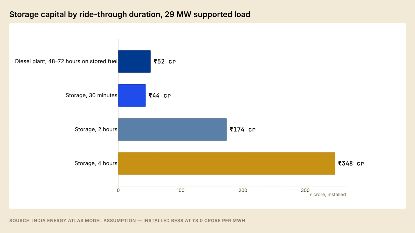
At the durations that Tier certification requires, storage is several times the capital cost of the diesel plant it would replace, for a fraction of the duration. No plausible near-term change in cell prices alters that conclusion, because the comparison is between an asset whose cost scales with energy stored and an asset whose cost scales with power delivered plus a very cheap energy store in the form of a fuel tank.
At short durations the position reverses. A battery sized to cover the transfer to generation replaces the uninterruptible power supply energy store that the facility was already purchasing, and delivers three capabilities the conventional string does not.
The first is longer bridging, which relaxes the generator start-time requirement and reduces the consequence of a single failed start. The second is grid-service capability: an asset of that size with a grid-facing inverter can participate in ancillary services and deviation settlement while remaining available for its primary duty. The third is lifecycle economics, with a replacement interval roughly double that of valve-regulated lead acid and a substantially smaller footprint.
IEEFA expects renewable generation paired with storage to reach cost parity with gas backup toward the end of this decade as cell prices continue to fall. The economics arrive before the compliance does. Uptime Institute Tier III and Tier IV certification requires on-site fuel for a duration that no economically sized battery satisfies, so until either the standard changes or a tenant waives certification, storage displaces the uninterruptible power supply layer and the first hour of generator runtime rather than the fuel farm.
State policy has begun to recognise the position. Gujarat's Data Centre Policy 2026–29 provides explicit capital support for battery energy storage alongside its tariff and duty provisions, which indicates that the storage-as-infrastructure argument has been accepted at state level even where the certification position has not changed.
5.1 Cell chemistry and thermal runaway containment #
The two lithium chemistries in stationary use differ on properties that decide the installation.
Property | Lithium iron phosphate | Nickel manganese cobalt oxide |
Energy density | Lower, larger footprint | Higher, smaller footprint |
Thermal runaway onset | Higher onset temperature | Lower onset temperature |
Oxygen release from the cathode | Minimal | Present, which sustains combustion internally |
Calendar ageing at a high state of charge | Slower | Faster |
Thermal runaway is a self-sustaining exothermic decomposition inside the cell. The heat released raises the temperature of adjacent cells, so the containment problem is propagation from cell to module to unit rather than the first cell. A cell also vents flammable gas, so an enclosed installation carries a deflagration hazard as well as a fire hazard, and the two are controlled differently.
The standards structure follows that physics. UL 9540A is the test method characterising propagation at cell, module, unit and installation level. NFPA 855 uses the resulting data to set separation distances, enclosure ratings, deflagration venting, detection and suppression. A battery system specified without the corresponding test report has been specified electrically and left undetermined on fire engineering.
Three consequences reach the design. Ventilation and gas detection are life-safety systems rather than comfort systems, and their supply and control arrangements follow from that. Suppression cools rather than extinguishes, because an internal decomposition supplies its own heat, so water volume and duration govern the outcome. Thermal management is itself a load during discharge, so a container cooled by its own air conditioning loses duration in high ambient unless that plant sits on the protected supply.
5.2 Backup duty against grid service #
The grid-service capability described above and the backup duty compete for the same asset, and the conflict is settled contractually before it is settled technically.
A battery held for backup sits at a high state of charge and cycles rarely, which minimises cycle ageing and maximises calendar ageing. A battery earning grid revenue cycles frequently across a wider state-of-charge range, which reverses the two. The design response is to reserve a fixed proportion of capacity for backup duty, permit the grid-facing control to operate only within the remainder, and implement that reserve as a hard floor in the control system rather than an operating instruction.
Two items follow. Capacity fade means the reserve is sized against end-of-life capacity, so installed energy at commissioning exceeds the autonomy requirement by the fade allowance over the warranted life. Availability commitments given to a system operator are drafted so that they never require discharge below the floor, since a settlement penalty is a smaller loss than an outage. Where the facility participates in the flexibility markets of Post 10, that floor bounds the accessible value stack.
5.3 Battery room ventilation and gas detection #
Ventilation of a battery space serves two duties that differ in trigger, in the flow required and in the consequence of failure, and a submission that treats them as one system has specified neither properly.
Duty | Trigger | Sized against | Chemistry it answers |
Thermal management | Continuous | Heat rejected by the cells and the conversion equipment at rated duty | Both lithium and lead acid |
Dilution ventilation | Continuous | The rate at which hydrogen is evolved during charging | Valve-regulated lead acid |
Emergency ventilation | Gas or off-gas detection | Removal or dilution of gas vented from cells | Lithium |
The distinction is chemical rather than administrative. A valve-regulated lead-acid string evolves hydrogen throughout charging, in normal operation and with nothing wrong, and at its highest rate during an equalising charge, so the space needs continuous dilution ventilation as a permanent condition. A lithium cell evolves nothing in normal operation and vents a flammable mixture only when it is failing, so the space needs no dilution ventilation in normal service and needs a detection-triggered response instead. A facility that replaces a lead-acid string with lithium and retains the previous scheme finishes with a ventilation system answering a hazard that no longer exists and no system answering the hazard that now does. Section 5.1 sets out the runaway physics that the second case is responding to.
Detection is arranged in layers, and the layers respond in a known order. A cell that is failing vents gas before it produces smoke and produces smoke before it produces flame, so an off-gas detector gives the earliest signal and is the only one that arrives while an intervention can still prevent propagation. Smoke detection follows, and heat or flame detection last. Each layer triggers a different action rather than the same alarm, which is the point of having more than one.
The action sequence is written before the incident and is executed in order: alarm at the site's continuously attended position; a command to the affected unit to stop charging and discharging and to open its direct current isolation, which removes the electrical energy still available to feed the fault; start of the emergency ventilation; notification to the fire service naming the chemistry and the hazard; and suppression released only against the criteria the fire strategy states. Isolation precedes ventilation because a unit still being charged is still adding energy to the cell that is failing.
One decision in that sequence has no universal answer and has to be taken explicitly. Ventilating a space that contains a flammable gas mixture removes the deflagration hazard by dilution, while introducing air to a space containing a fire supplies it with oxygen. Which hazard governs depends on the installation, and the answer for an outdoor container fitted with deflagration vent panels is not the answer for a room inside an occupied building. That decision, and the UL 9540A data that supports it, is the substance of the fire engineering submission described in section 5.1, and a submission that does not resolve it has left the control philosophy undetermined.
Two consequences follow for the equipment. The space is treated as one in which a flammable atmosphere can occur, so electrical equipment within it and the fans and motors in the exhaust path are selected on that basis rather than as ordinary building services. Detector placement follows the gas rather than a convention: hydrogen collects at high level, while the vent mixture from a lithium cell contains both lighter and heavier components, so head positions are taken from the test data for the product installed rather than from a rule applied to every chemistry.
Emergency ventilation, gas detection and the battery management system are all supported from a supply that survives the event, for the same reason the generator auxiliaries in section 2.8 are. The circumstance most likely to require them is a loss of the normal supply, and a life-safety system fed from the board that has just failed is a system that exists on the drawing. Access is designed on the same assumption: a person must be able to leave the space with a unit in alarm, so door swing, travel distance and the position of the manual controls outside the space are settled at layout stage.
The diligence set for this material is small and specific. It comprises the fire strategy naming the chemistry and the governing hazard, the UL 9540A report at the level the installation requires, the emergency response plan lodged with the local fire service, and the functional test records described in section 8.3.
6. The scale of the incumbent position #
The diesel plant installed across India's operating data centre fleet consumes fuel at a scale that makes the alternatives worth engineering rather than merely worth discussing.
A facility of moderate size operates a fleet of mid-sized sets and runs them across mandatory monthly testing, grid outages and planned maintenance. The hours are small as a fraction of the year and large as an absolute quantity of fuel, because the plant is sized against the whole facility load and burns at that rate whenever it runs.
Quantity | Value |
Sets installed at a 50 MW facility | 10–15 |
Rating per set | 2–2.5 MW |
On-site diesel storage | 200,000–500,000 litres |
Annual run hours | 200–500 |
Annual consumption, one facility | 1.5–3 million litres |
Annual fuel cost, one facility | ₹12–25 crore |
Annual carbon dioxide, one facility | 4,000–7,500 tonnes |
Annual consumption across the operating fleet | 300–500 million litres |
Annual consumption on the 2030 capacity trajectory | 2–3 billion litres |
Source: India Data Centre Review 2026, Chapter 6, operator survey; emission factors from the Central Pollution Control Board. Figures are quoted at the locked edition snapshot of 13 July 2026.
Two properties of that table carry the argument. The consumption is produced mainly by routine testing and short outages rather than by a rare extended event, so it is insensitive to the resilience case and sensitive to the operating regime, which is the reason section 8.2 treats the exercise schedule as an emissions decision as well as a maintenance one. The trajectory row scales with installed capacity rather than with any change in practice, so fleet consumption grows with the sector unless the architecture changes.
That is the position any alternative has to displace, and it is large enough that the fuel line alone justifies the engineering study at individual facility level.
7. Worked comparison #
Model assumption — 20 MW IT block, twenty-year evaluation, 11% discount rate
Diesel with VRLA UPS | Diesel with lithium UPS | Gas with lithium UPS | |
Generator plant capital | ₹52 crore | ₹52 crore | ₹75 crore |
Energy storage capital | ₹28 crore | ₹42 crore | ₹42 crore |
Total capital | ₹80 crore | ₹94 crore | ₹117 crore |
Storage replacement cycles over twenty years | Two | One | One |
Fuel cost exposure | Highest | Highest | Lower per unit |
Emissions exposure above the threshold | Yes | Yes | Substantially reduced |
Grid service capability | None | Available | Available |
The first two columns produce broadly comparable present values, because the higher capital cost of lithium is offset by avoiding a replacement cycle. The third carries a higher capital cost that is recovered through fuel cost and that removes the regulatory exposure described in section 3.
The decision is not made on the net present value line. It is made on two rows that sit below it: whether the facility can access a grid revenue or tariff position through its storage asset, and what value is placed on removing an emissions exposure whose regulatory treatment is two decades old and under periodic judicial attention.
7.1 Boundaries of the comparison #
The comparison holds under four conditions, each a point at which to recalculate rather than adopt the result.
Condition assumed | Where it fails | Effect on the ranking |
Gas connection available at adequate pressure and volume | Site outside a city gas distribution network | The gas column absorbs the connection works and the authorisation period, and the exercise compares two projects rather than two configurations |
Annual run hours at the assumed level | Weak point of connection, single utility feed | Fuel difference displaces capital difference as the deciding term |
Diesel at the commercial pump rate, gas under contract | Either price moves independently | Ranking follows whichever fuel price moved, so both are run across a range |
Emissions exposure carried at zero cost | Any revision of the above-threshold standard | Ranking shifts toward gas; the largest single sensitivity in the exercise, and the one least amenable to measurement |
8. The testing regime and its evidence #
A backup claim describes behaviour under a condition that has not yet occurred, and the only evidence for it is a test reproducing that condition. The testing regime therefore belongs in the specification, and it divides into three stages.
Factory acceptance, before dispatch. The set is proved against its site rating rather than its reference rating, and against the performance class the specification names, with the step load sequence applied and the excursions recorded. A test at reference conditions proves the machine rather than the installation.
Integrated systems testing, at commissioning. The test that carries the claim is a full-load black building test, in which incoming supply is removed, the sequence in section 1.1 runs unassisted, and the facility is held on generation long enough to reach steady thermal conditions in the engines, the exhaust and the cooling plant. Load banks stand in for tenant load in unoccupied halls, and the test is repeated with a set out of service to prove the redundancy count of section 2.
Periodic exercise, through the operating life. Monthly exercise of standby plant is a condition of Tier III and Tier IV certification. The requirement behind it is that the set reaches operating temperature under a load large enough to avoid the incomplete combustion, unburnt fuel accumulation and bore glazing that follow prolonged light loading. Where the load available for testing is small relative to the plant, a load bank supplies the difference.
NFPA 110 supplies the classification vocabulary, describing an emergency power supply system by the time within which power must be available at the load, the duration for which it must operate without refuelling, and the consequence of a failure to supply. Those parameters belong in the specification rather than the equipment schedule.
Four records constitute the evidence of a backup claim, and they are the four to request in diligence: the site-rating certificate against the design ambient, the integrated systems test report covering the black building test and the redundancy case, exercise records showing load achieved rather than time run, and the fuel analysis history against the storage volume held.
8.1 Load banks and the structure of a proving test #
The load a proving test requires does not exist in an unoccupied hall, and where it does exist it belongs to a tenant who cannot have it stepped, held and removed to a schedule. A load bank supplies a controllable and repeatable load in its place, and the type of bank chosen determines how much of the plant the test actually proves.
A resistive load bank switches resistive elements in steps and presents unity power factor. It loads the engine to its real power rating and proves the fuel system, the cooling system, the exhaust at full mass flow and the governor's response to a step. It leaves the alternator below its rated current, because the machine is rated in apparent power at a lagging power factor, and a unity-power-factor test therefore takes the excitation system nowhere near its rated operating point. A set proved on resistive load alone has been proved as an engine and not as a generating set.
A reactive load bank adds inductive elements so that the combined load sits at the machine's rated power factor. It proves the alternator's current rating, the excitation at rated field, and the reactive load sharing between paralleled machines that section 2.3 describes, which a resistive bank cannot exercise at all. Where the facility can present a leading power factor at light load, from the input filters described in section 2.6 or from power factor correction, a capacitive case proves the under-excitation behaviour of section 2.7. That case is normally omitted, and it is the one that produces a loss of voltage control in service.
The connection point decides the extent of the installation under test. A bank connected at the generator bus proves the machines and their switchgear and nothing downstream. A bank connected at a distribution board proves the busway or cable, its protection and its volt drop as well, and where a black building test is the objective the connection is chosen so that the whole path being claimed is energised. The distribution architecture that path runs through is the subject of Post 4.
Test case | What it proves | What it leaves unproved |
Resistive load applied in steps | Governor response, step acceptance, and fuelling against the smoke limit | The alternator current rating and the excitation at rated field |
Resistive load held to thermal stability | Cooling, exhaust and hall ventilation at steady state, and the fuel transfer system keeping pace | The reactive behaviour of the plant |
Combined resistive and reactive at the rated power factor | Alternator rating, excitation at rated field, and reactive load sharing between sets | Behaviour under a leading load |
Leading power factor case | The under-excitation limit and voltage control at light load | — |
Load rejection in one step | Overspeed and over-voltage excursion on removal of load | — |
Redundancy case with one set out of service | The installed count against the design contingency | — |
Retransfer to the utility under load | The return of supply and the closing arrangement | — |
The test runs in a fixed order, and the order is part of the deliverable. Pre-test checks and a safety case for the deliberate removal of supply come first, then a baseline record of the plant's condition. The incoming breaker is opened. The sequence of section 1.1 then runs unassisted, and any intervention by an attending engineer invalidates the result for the purpose it was performed. Load is applied in the steps the sequencing scheme defines, built to full load, and held until the engines, the exhaust and the cooling plant reach steady thermal conditions. The redundancy case is then repeated with a set out of service. Load rejection follows, because a governor tuned only for acceptance will overshoot on removal, and a plant that has never been proved on rejection will discover that behaviour during a real trip. Retransfer to the utility closes the test, and a post-test inspection completes it.
The acceptance criteria are written before the test rather than assessed after it. They comprise the frequency and voltage excursion and the recovery time for each step against the performance class of ISO 8528, the steady-state bands, the real and reactive load sharing balance across the running sets, coolant and exhaust temperatures at thermal stability, fuel consumption against day tank level and the transfer system's ability to keep pace, voltage distortion at the bus with the non-linear load connected as section 2.6 describes, and the boundary noise measurement of section 3.4 where the test provides the only opportunity to take one with the plant fully loaded.
Instrumentation decides whether the record means anything. A switchboard meter averages over a window far longer than the excursions being measured, so the transient behaviour is captured with a recorder or power quality analyser at the bus, and the records are time-synchronised so that the sequence can be reconstructed afterwards rather than inferred.
Six defects account for most of what a full proving test finds, and each of them is invisible to a monthly no-load exercise: a sequencing scheme that starts two large motors together, a fuel transfer system that cannot match consumption at full load, hot air recirculating into the radiator intakes as section 2.9 describes, reactive load sharing errors between paralleled machines, exhaust back-pressure above the manufacturer's allowance, and a battery charger fed from the board that the test has just de-energised.
8.2 The maintenance and testing calendar #
Three drivers set the calendar and they do not agree with one another. The manufacturer's schedule states intervals in running hours or elapsed calendar time, whichever falls first. The certification and consent regime imposes the monthly exercise required for Tier III and Tier IV and whatever testing the pollution control board attaches to the consent. The site's own condition monitoring produces findings that move individual items earlier.
The running-hour and calendar distinction matters more for standby plant than for any other machine on a site, because standby sets accumulate calendar time at the normal rate and running hours at a small fraction of it. A schedule read as running hours alone leaves lubricating oil, coolant, hoses, belts, batteries and stored fuel to age in place while the counter barely moves. Post 9 sets out the adjustment Indian ambient, dust and humidity require to manufacturer-standard intervals.
Activity | Basis of the interval | What the record evidences |
Visual inspection, fluid levels and alarm state | Site routine between exercises | Leaks, consumption and unacknowledged alarms |
Exercise under load | Monthly, as a condition of Tier III and Tier IV certification | The start chain, load acceptance, and the temperature reached |
Start battery capacity or impedance measurement | Trended against the manufacturer's guidance | The most common single cause of a failed start, section 2.8 |
Water draw-off from tank low points | Residence time of the stored volume, section 2.10 | Whether water accumulates faster than it is removed |
Fuel sampling and laboratory analysis | Residence time of the stored volume | Degradation in storage, against a dated series |
Fuel polishing | Set from the same calculation | That the stored volume has been circulated and filtered |
Lubricating oil sampling | Running hours or elapsed time, whichever falls first | Wear metals, fuel dilution and soot loading |
Coolant analysis | Elapsed time | Inhibitor concentration protecting the jacket and the charge air cooler |
Air filter restriction and radiator core condition | Site condition, more frequent at dusty locations | Whether intake and cooling paths remain inside their allowances |
Exhaust back-pressure measurement | At commissioning, and after any change to the route or the after-treatment train | That the budget of section 3.2 remains intact |
Protection, regulator and governor settings verification | At commissioning, and after any change | That the settings in service are the settings designed |
Real and reactive load sharing verification | After any change to the control scheme | That the plant divides load as designed, section 2.3 |
Integrated systems test with a set out of service | The certification regime the facility holds | The redundancy count under a real failure |
Storage capacity test against the commissioning baseline | The method the warranty states | Degradation against the warranted trajectory, section 8.3 |
Detection and suppression functional tests | The fire strategy | That the life-safety sequence of section 5.3 operates |
Boundary noise measurement | At commissioning, and after a change to plant or treatment | The consent condition of section 3.4 |
Numeric intervals are deliberately absent from that table. They are properties of a specific engine, a specific storage volume and a specific site, and a calendar copied from another facility is the mechanism by which an interval becomes wrong. The basis column is transferable; the number is not.
The exercise record is the item most often misread. A record of hours run is evidence that the set was started, and a record of load achieved is evidence that it worked. The two diverge because light-load running is the condition the exercise exists to avoid: incomplete combustion leaves unburnt fuel and lubricating oil in the cylinder and the exhaust, deposits glaze the bore, and the machine's ability to make rated power falls. Once glazing is established the remedy is a sustained period at high load or a mechanical de-glaze, both of which are interventions rather than routine work. A log showing many hours and no load is therefore evidence of a developing defect rather than of compliance, and it is the single most useful document to request in operational diligence.
Deferral is the second item to inspect. Maintenance deferred on standby plant has no immediate consequence, no operational signal and no complaining user, which makes it the easiest maintenance on a site to postpone and the most consequential to lose. The deferral register, rather than the completion rate, is what shows whether the regime is real. Method of procedure and change control around this work belong to Post 9 §5.2.
The spares holding is a procurement decision taken at the same time as the plant, not an operations decision taken after a failure. The parts that convert a fault into an extended loss of redundancy are the ones with import lead times: the voltage regulator, the rotating diodes, the governor actuator, the turbocharger, the starter motor, control cards and the battery charger. A holding covering those items is inexpensive against the plant cost and is either bought at order or bought at a premium under pressure.
8.3 Storage system commissioning and its evidence #
A storage system arrives with part of its life already consumed, which is where its commissioning record has to begin. Calendar ageing starts at manufacture rather than at energisation, so the manufacturing date, the state of charge maintained in transit and storage, and the elapsed time before commissioning are all recorded and checked against the warranty, and a system that has waited in a warehouse through a hot season has spent warranted life that no later test can recover.
Stage | Test | What it establishes |
Before energisation | Insulation resistance, polarity, connection torque records and earthing | That a direct current joint will not become a heating fault in service |
Control chain | Cell monitoring to battery management to conversion to plant control, link by link and then end to end | That every command path exists, operates and reports |
Reserved capacity | A commanded discharge that would cross the reserved floor | That the floor of section 5.2 is a control limit rather than an operating instruction |
Performance | Measured discharge at rated power to the defined end point | Usable energy against the warranted figure, and the baseline for every later test |
Performance | Round-trip efficiency measured at the point of connection | Conversion and auxiliary losses inside the measurement boundary |
Performance | Auxiliary draw of the thermal management plant during that discharge | The term that reduces duration in high ambient, section 5.1 |
Dynamic | Response to a step command on the grid-facing function | Whether the asset meets the requirement of the market it is offered into |
Dynamic | Transition between storage and generator plant under load | That the ride-through hierarchy of section 1 closes without a gap |
Life safety | Detection at each layer, ventilation start, isolation command and emergency stop | That the sequence of section 5.3 operates as written |
Three of those rows carry more weight than the rest. The measured discharge is the baseline against which every subsequent capacity test is compared, and without it a degradation claim years later has nothing to be measured against, which makes its absence a warranty problem rather than a commissioning omission. Round-trip efficiency measured at the point of connection rather than at the direct current terminals is the only version of the figure that includes the conversion equipment and the auxiliaries, and it is the version the facility's energy accounting needs. The reserved floor test is the only evidence that the floor is enforced in the control system, and it is performed by commanding a discharge that would breach it and demonstrating that the command is refused.
The dynamic tests reach outside this post. The signal-to-response path for a grid-facing function, including the telemetry and the latency it must meet, is the subject of Post 10 §6.1, and the commissioning test here establishes only that the asset's own response satisfies whatever that path requires.
Five documents constitute the evidence set for a storage installation. The propagation test report is provided at the level the installation requires, under UL 9540A. The fire engineering narrative sets out the separation distances adopted and the data supporting them, against NFPA 855. The commissioning record includes the baseline capacity test. The warranty document states its measurement method together with its ambient and cycling assumptions. The emergency response plan is lodged with the local fire service.
The warranty deserves separate attention because the forms are not comparable. A guarantee expressed in cycles at a stated depth of discharge, temperature and rate answers a different question from one expressed as energy throughput, and both answer a different question from a capacity retention guarantee. None of the three can be tested at all unless the measurement method is stated and a commissioning baseline exists, so the two documents are read together or neither means anything.
Forward look #
Three developments would change the analysis materially.
The first is any revision of the emission standard applicable to engines above the current threshold. A revision would apply to installed plant as well as to new plant if it followed the pattern of the retrofit mandate below the threshold, which would convert a design allowance into a capital requirement across the operating fleet simultaneously.
The second is last-mile gas connectivity into the established data centre clusters. The trunk infrastructure and the authorisation framework are both in place, and the constraint is the dedicated industrial connection. The United States precedent suggests the switch completes quickly once that threshold is crossed.
The third is whether Uptime Institute or an equivalent certification body recognises storage against the on-site fuel requirement. That single change would move battery storage from the uninterruptible power supply layer into direct competition with the fuel farm, and would reverse the conclusion in section 5.
FAQ #
How many generators does an Indian data centre need? More than a sizing tool at reference conditions returns. Ambient, altitude and humidity derate output materially, and the derating must be applied before the redundancy count is established. Section 2 sets out the derivation.
Does CPCB IV+ apply to data centre generators? No. CPCB IV+ and the retrofit mandate apply to sets up to 800 kW of gross mechanical power. Data centre sets are larger and fall under a separate standard phased in between 2003 and 2005.
Can battery storage replace diesel generators? Not at the durations Tier III and Tier IV certification require, where storage costs several times the diesel plant for a fraction of the duration. At short durations it replaces the uninterruptible power supply energy store and adds grid-service capability.
Is gas backup viable in India? Where the site sits within a city gas distribution network with adequate capacity. The trunk network and authorisation framework are in place; the constraint is the dedicated industrial connection to the site, which requires its own authorisation and construction period.
What is the supply risk in gas backup? A majority of India's LNG imports transit the Strait of Hormuz and domestic production covers approximately half of national demand. Data centres are not a priority allocation category, which is the argument for retaining diesel as a secondary fuel rather than removing it.
What does a full-load black building test have to include? Removal of the incoming supply, an unassisted automatic sequence, restart of the mechanical plant under the sequencing scheme, load banks making up the balance to full load, a hold long enough to reach steady thermal conditions, a load rejection case, and a repeat with one set out of service. Section 8.1 sets out the test cases and what each of them proves.
Sources #
Central Pollution Control Board, genset emission notifications and retrofit emission control device mandate
DieselNet, India genset emission standards, engines above 800 kW
Uptime Institute, Tier Standard: Topology
Standards and instruments named in the text: ISO 3046, ISO 8528, IEC 62040-3, NFPA 110, NFPA 855, UL 9540A, Petroleum Act 1934 and Petroleum Rules 2002, Air (Prevention and Control of Pollution) Act 1981, Environment (Protection) Act 1986 and Noise Pollution (Regulation and Control) Rules 2000. Each is named at instrument level; no clause, limit value or class threshold from any of them appears in the text.
PNGRB, city gas distribution authorisation and pipeline data to June 2025, via IDCR 2026
IEEFA, renewable-plus-storage backup parity analysis, via IDCR 2026
Grid Strategies, National Load Growth 2025, via IDCR 2026
Government of Gujarat, Data Centre Policy 2026–29, June 2026 (via NASSCOM Public Policy)
India Data Centre Review 2026 (v2.3, edition cutoff 28 July 2026), Chapter 6 — India Energy Atlas
Generator sizing, the storage duration comparison and the twenty-year configuration comparison are modelled by India Energy Atlas and are labelled as model assumptions. IDCR 2026 figures are quoted at the locked edition snapshot of 13 July 2026; live Atlas products may carry newer records.
This post was revised against the measured GenAI load-profile analysis — see the working note for the load derivation, ramp rates and the peak-to-nameplate ceiling.
Read the full series — The Indian Data Centre Playbook, twelve parts from unit economics to exit.
Next in the series — Part 7: Powering the Build. The landed cost stack from generation tariff to meter, charge by charge.
India Energy Atlas builds India's grid intelligence layer. See energymap.in/pricing.
Sources & method
- Central Pollution Control Board, genset emission notifications and retrofit emission control device mandate - DieselNet, India genset emission standards, engines above 800 kW - Uptime Institute, Tier Standard: Topology - Standards and instruments named in the text: ISO 3046, ISO 8528, IEC 62040-3, NFPA 110, NFPA 855, UL 9540A, Petroleum Act 1934 and Petroleum Rules 2002, Air (Prevention and Control of Pollution) Act 1981, Environment (Protection) Act 1986 and Noise Pollution (Regulation and Control) Rules 2000. Each is named at instrument level; no clause, limit value or class threshold from any of them appears in the text. - PNGRB, city gas distribution authorisation and pipeline data to June 2025, via IDCR 2026 - IEEFA, renewable-plus-storage backup parity analysis, via IDCR 2026 - Grid Strategies, National Load Growth 2025, via IDCR 2026 - Government of Gujarat, Data Centre Policy 2026–29, June 2026 (via NASSCOM Public Policy) - India Data Centre Review 2026 (v2.3, edition cutoff 28 July 2026), Chapter 6 — India Energy Atlas Generator sizing, the storage duration comparison and the twenty-year configuration comparison are modelled by India Energy Atlas and are labelled as model assumptions. IDCR 2026 figures are quoted at the locked edition snapshot of 13 July 2026; live Atlas products may carry newer records. Photography: - Photo by Abhijeet Gaikwad on Unsplash (https://unsplash.com/photos/a-factory-with-a-lot-of-green-and-white-machinery-wUuq69GGLnU?utm_source=india_energy_atlas&utm_medium=referral)