
Data Centre Electrical Topology: Redundancy, Fault Domains and Capital Cost in Indian Conditions
How redundancy topology determines capital cost, tenant addressability and exit value for Indian data centres, covering the redundancy notations, fault domain sizing, three costed topologies, and the derating factors imported standards do not address.
The short answer. The redundancy topology of an Indian data centre determines its capital cost, the population of tenants able to lease it, and the yield at which an institutional buyer will underwrite it. The decision should be made against tenant addressability rather than against the value of service level credits avoided, because the second calculation systematically understates what the topology is worth.
This post sets out how electrical redundancy is specified, what each topology costs, how fault domain sizing interacts with the occupancy ramp, and which Indian environmental and regulatory conditions require departure from the imported design standards. It is written for the design engineer specifying the system, the developer approving the capital, and the investor assessing whether the specification supports the business plan.
The topology decision is made once, early, and is expensive to reverse. Distribution architecture is embedded in the building structure, the electrical room footprint and the switchgear procurement, so a facility built to one topology cannot be economically converted to another after commissioning. It therefore has to be made against the facility's intended tenant population over its whole life rather than against the requirements of the first tenant to sign.
1. Redundancy notation #
Notation | Configuration | Concurrent maintenance | Fault tolerance |
N | Exactly the capacity required | No | No |
N+1 | One redundant unit across the system | Partial | No |
N+2 | Two redundant units | Yes for most components | No |
2N | Two complete independent systems | Yes | Yes |
2(N+1) | Two systems, each internally redundant | Yes | Yes, with margin |
Distributed redundancy | Three systems each carrying two-thirds of load | Yes | Yes |
Two properties determine commercial outcomes and are routinely conflated in marketing material.
Concurrent maintainability means any capacity component or distribution path can be removed from service for planned maintenance with the critical load fully supported. It permits an operator to service an uninterruptible power supply or a transformer without requiring an outage window from the tenant, which matters because tenants with continuous operations will not grant one.
Fault tolerance means a single unplanned failure anywhere in the system does not affect the critical load. This is a strictly stronger condition than concurrent maintainability, because a planned removal from service is a controlled event with the system reconfigured in advance, while a fault is an uncontrolled event that must be survived in whatever configuration exists at the time.
A facility described as concurrently maintainable and partially fault tolerant is not described against any defined standard. The question that resolves the specification is which specific distribution paths are single-fault tolerant and which are not, and the answer should be traceable on the single-line diagram rather than asserted in a summary.
1.1 The standards basis for the notation #
The notation counts components and says nothing about how they are connected, so it does not by itself classify a facility. The classification in general use is the Uptime Institute Tier Standard: Topology, which defines its classes against functional requirements rather than a prescribed equipment list, with the companion Tier Standard: Operational Sustainability covering management practices. Each class adds to the one below it, moving from redundant capacity components, to multiple independent distribution paths of which one is required to serve the load at any time, to fault tolerance with compartmentalisation and continuous cooling.
Certification is awarded in three forms that are not interchangeable: against design documents, against the constructed facility, and against operational sustainability. Each is awarded to a defined boundary, normally one block on a phased campus. Four questions establish what a claim contains: which form was awarded, on what date and against which revision of the design, which blocks fall inside the certified boundary, and whether any subsequent modification has been re-assessed. A facility described as built to a class, without an award against the constructed facility, has been assessed on paper, and a paper assessment does not survive the value engineering that occurs between design freeze and commissioning.
1.2 Common-mode failure paths #
Redundancy notation counts units on the assumption that the units are independent. Independence fails wherever two nominally separate systems share a physical or procedural element, and the shared element is frequently absent from the single-line diagram because it is not power plant.
Shared element | How independence is defeated |
Control and monitoring | One controller or settings file governs both systems |
Transfer logic | One scheme decides transfer for both sides |
Battery room cooling | Both stored-energy installations in one conditioned space |
Cable route or riser | Both distribution paths through one shaft or trench |
Earthing and bonding network | One network, by design, common to both sides |
Upstream busbar | Two incomers from one bus section at the feeding substation |
Physical separation converts a count into fault tolerance, and each of its elements is a building decision rather than an electrical one, which is why the topology has to be settled before the structural design is frozen. Two feeders taken from the same busbar share its protection and its maintenance outages, so the pair is a single source for the purpose of the redundancy count until the utility confirms that they originate on separate bus sections.
The test on a drawing is mechanical. Trace one rack outlet back to the point of connection twice, once along each declared path, and mark every node the two traces share. A fault-tolerant design has no shared node below the point of connection, and a concurrently maintainable design may have several, each of which should correspond to a procedure that services it without interrupting the load.
1.3 Single-line diagram conventions and the complete drawing #
The trace test in the preceding subsection assumes a drawing that supports it, and many do not. The single-line diagram is the document on which every topology claim is either visible or absent, so the conventions it follows determine what a reviewer can establish and what has to be taken on assurance.
The convention itself is a compression. Three conductors of a three-phase circuit are drawn as one line, and the drawing records the electrical arrangement rather than the physical route, so two conductors drawn apart on the page may share a trench and two drawn adjacent may run in separate buildings. Physical separation is therefore a property the single line cannot show, which is why the shared-route element in the common-mode table above has to be confirmed against a containment layout rather than against the single line. Graphical symbols are standardised in IEC 60617, and a set of drawings using a manufacturer's house symbols instead imposes a translation step on every reviewer and every study that follows.
Element | What the drawing has to state |
Sources | Point of connection, each incomer and each generator, with rating and voltage |
Switching devices | Tag, type, interrupting rating, and normal state |
Bus sections and ties | Section boundaries, and the normal state of every tie and coupler |
Transformers | Rating, ratio, vector group, impedance, cooling class and tap range |
Neutral earthing | The arrangement at each voltage level and the position of every earth point |
Instrument transformers | Ratio, class, and the circuits each one feeds |
Protection | Device tag and protection function at each position |
Cables and busway | Type, size, and run or circuit designation |
Metering | Position of the tariff meter and of every check meter |
Loads | Board designation, and the group of load each board serves |
Revision block | Status, revision number, date, and the change the revision records |
Two of those rows decide whether the drawing can be used at all. The normal state of every switching device is the first, because a diagram that does not distinguish a normally open tie from a normally closed one cannot establish either the fault domain or the result of the two-path trace, and a reviewer who assumes the state has produced an opinion about a system that may not exist. The revision block is the second, because a topology claim is a claim about installed plant, and a drawing evidences installed plant only where it is marked as recording it.
The drawing also has a defined silence. It carries power circuits and omits control wiring, interlocking, protection signalling and operating sequences, which is the mechanism by which the common-mode elements in section 1.2 stay invisible during a review conducted on the single line alone. Those elements live on companion drawings, and the set is incomplete without them.
Companion drawing | What it carries that the single line does not |
Protection and metering schematic | Current and voltage circuits, relay inputs, tripping logic |
Control and interlock schematic | Transfer logic, permissives, and the interlocks between devices |
Earthing and bonding layout | Electrode array, the bonding network, and each connection point |
Containment and route layout | Which paths share a trench, riser or room |
Cable and busway schedule | Size, length, installation method and the derating applied |
Load schedule | Connected and diversified load per board, phase by phase |
A drawing exists in three states at once, and keeping the three consistent is the document control problem an operating facility has to solve.
State | What it represents | Custody and use |
Issued for construction | The design at freeze | The contractor's basis for installation |
As-built | What was installed, with field changes incorporated | Handover deliverable, and the basis of every study |
Operational | The current arrangement including later modification | The control room copy, updated under change control |
The three drift apart whenever a modification is executed and closed out without a drawing change, and the drift is normally discovered during an incident, when the operational copy is the document someone is reading under time pressure. The diligence step is to ask for the operational drawing and the modification register together and compare their dates, because a register carrying entries after the drawing's last revision states the size of the gap directly.
2. The distribution chain #
Each stage of the chain from the grid connection to the rack outlet carries its own redundancy decision, and the weakest stage governs the resilience of the whole.
Stage | Typical equipment | Redundancy commonly applied |
Grid connection | 220 kV or 132 kV incomer, two sources preferred | Two incomers from separate substations where available |
Primary transformation | 220/33 kV or 132/33 kV power transformers | N+1 minimum |
MV distribution | 33 kV or 11 kV switchgear, ring or radial | Two bus sections with a tie |
Standby generation | 2–3 MVA sets, paralleled | N+1 to 2N |
Transfer | Automatic transfer switches at MV or LV | Matched to the downstream topology |
Secondary transformation | 33/0.415 kV or 11/0.415 kV cast resin | 2N in most fault-tolerant designs |
Uninterruptible power supply | Static double conversion, lithium or VRLA | N+1, 2N or distributed |
LV distribution | Power distribution units, remote power panels, busway | 2N to the rack |
Rack | Dual-corded rack PDUs, A and B feeds | 2N at the outlet |
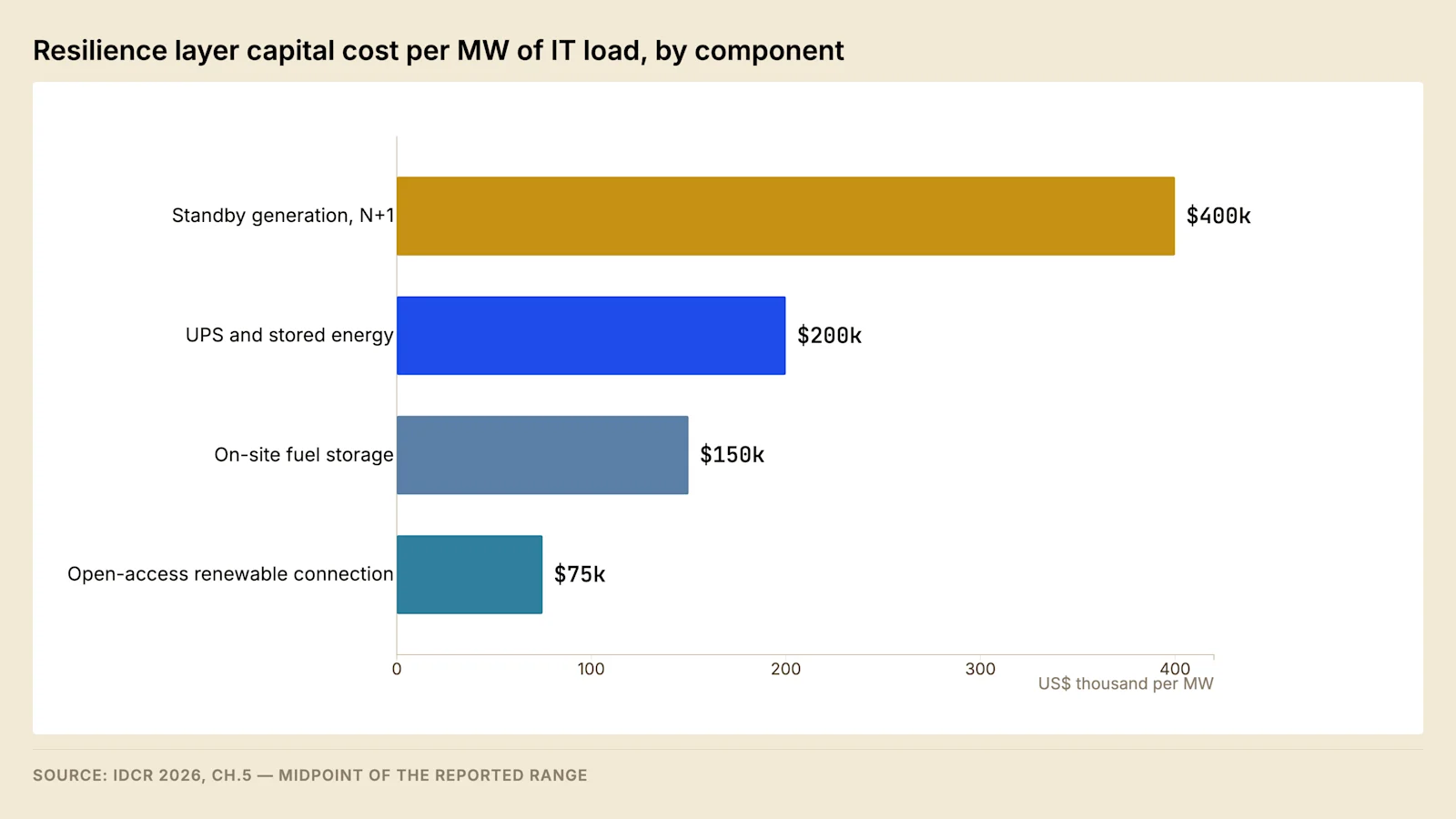
Everything below the grid connection exists to close a single gap. Indian grid availability sits below the level a colocation lease commits to, and the difference is manufactured on site through stored energy, standby generation and on-site fuel. The India Data Centre Review 2026 prices that layer by component, and it represents a material fraction of total project cost that buys no additional revenue-generating capacity.
Field note. The A and B feed discipline fails at the rack more often than anywhere else in the chain. A dual-corded server connected to two outlets on the same rack power distribution unit is a single point of failure inside a fault-tolerant facility, and the failure is invisible on the single-line diagram because the diagram terminates at the PDU. Operators running mixed-tenant halls should audit outlet-level feed assignment on a recurring basis rather than at commissioning only.
2.1 Static transfer switches and dual-corded load #
A static transfer switch supplies a single-corded load from two sources and transfers between them within a fraction of a cycle using semiconductor devices rather than contacts. Three conditions govern its behaviour.
The sources must sit inside a voltage and phase-angle window for the transfer to occur without connecting them out of phase. Where they drift outside it, the switch inhibits the transfer or executes it with a deliberate dead time, and the load rides through on the hold-up energy stored in its own power supply. Equipment tolerance to a short interruption is a published characteristic of that power supply, and it is the quantity against which a transfer time should be assessed.
Where a transformer sits below the switch, a transfer applies voltage to a core carrying residual flux, and the resulting inrush can operate protection on the source being transferred to.
The third condition is the most consequential. A switch connected to both sides of a two-system design is a point at which those systems meet, and an internal device that fails conducting connects the two sources to one another. The rule that follows is that a dual-corded load has no need of a static switch, because its own two power supplies perform the transfer with no shared node. Static switches belong only where single-corded equipment has to be served inside a fault-tolerant facility, and every such position should sit on a register reviewed whenever equipment is replaced.
Event | Consequence for the load |
Preferred source sag inside the equipment tolerance | Transfer completes, load unaffected |
Sources outside the phase window | Load rides through on power supply hold-up |
Transformer energised on transfer | Inrush may operate protection on the alternate source |
Internal device fails conducting | Independence between the two systems is lost |
2.2 Uninterruptible power supply topologies #
The uninterruptible power supply is the stage at which the topology decision has its largest effect on operating cost, because its losses are continuous and because the redundancy count sets the load fraction at which each unit runs.
Mode | Normal path | Behaviour on an input disturbance | Conditioning |
Double conversion | Rectifier, direct current bus, inverter | Inverter continues from stored energy, no transfer | Full; waveform synthesised |
Economy or multi-mode | Static bypass, inverter in standby | Transfer to the inverter on detection | Partial until transfer completes |
Rotary and diesel-rotary | Machine in line with the load | Kinetic energy bridges to engine start | Full, different maintenance regime |
Conversion loss has a component that is approximately fixed and a component that varies with load. Magnetics, control electronics and the unit's own cooling draw power whether or not the unit is loaded, so efficiency falls as the load fraction falls, and it falls steeply toward the bottom of the range. Redundancy places the plant on that part of the curve by construction, which is the mechanism by which a topology decision becomes a permanent energy cost. The loss enters the facility's own consumption, and its share of the non-IT load is set out in Post 5.
Configuration | Load fraction per unit in normal operation |
N | Design maximum |
N+1 | Design maximum less the redundant unit's share |
Distributed redundancy | Two-thirds of unit rating |
2N | At most half of unit rating |
Two failures recur in operation. The first is a facility running in economy mode when its design assumed double conversion, a settings decision taken for efficiency and rarely recorded against the design basis, so the conditioning the design assumed is absent and the first evidence of it is a tenant reporting equipment trips during a supply disturbance. The second is an open circuit in a stored-energy string, which gives no symptom until a discharge is required. Four questions establish the position: which mode is in service rather than which modes are available, the date and result of the last discharge test, the load at which it was performed, and the age of the strings.
2.3 Busway and cable as distribution media #
The current a conductor carries continuously is set by the temperature its insulation tolerates, so a cable rating falls with ambient temperature, with the number of circuits grouped in one containment, and with the installation method. In an Indian cable basement carrying many circuits those factors compound, and a cable selected from a tabulated rating without them is undersized in service. Busway is rated as an assembly at a stated ambient, so its rating is insensitive to the installation while its ambient limit is absolute.
Attribute | Cable and panelboard | Busway |
Adding a circuit | New cable pull, containment permitting | Tap-off box onto an existing run |
Grouping and ambient | Factors compound | Rating stated for the assembly |
Short-circuit withstand | Calculated for the installation | Stated by the manufacturer |
Fault location | By isolation along the route | To the section between joints |
Characteristic failure | Termination heating | Joint heating from loss of bolt tension |
Surveillance | Thermography at terminations | Thermography and torque check at joints |
The busway failure mode is progressive. A joint loses clamping force, contact resistance rises, temperature rises, and the temperature accelerates the further loss of force. The progression is detectable by infrared survey long before it becomes an arcing fault, so a facility using busway without a scheduled thermographic survey removes its only warning. The choice between the two media is settled by the expected rate of change in the hall, because every change in a cable-fed hall requires access to a panel serving live load.
2.4 Switchgear construction and the insulating medium #
Switchgear specification is routinely written around two terms that describe different things. The insulating medium holds off voltage between live parts and earth in normal service and determines the clearances, the enclosure and the sensitivity of the assembly to its environment. The interrupting medium is what the arc is drawn in when the contacts part, and it determines the interrupting duty, the contact life and the maintenance regime. An assembly can be air-insulated with vacuum interrupters, gas-insulated with vacuum interrupters, or gas-insulated with gas interruption, and the three behave differently in a humid coastal plant room while carrying the same rating on a schedule.
Medium | Role in the assembly | Behaviour that governs selection |
Air | Insulation between live parts | Clearances set the footprint; pollution and moisture reach the insulation directly |
Sulphur hexafluoride | Insulation, and interruption in some designs | Sealed enclosure isolates the insulation from the room; density has to be monitored and leakage managed |
Vacuum | Interruption only | Arc extinguishes at the first current zero; the failure mode is loss of vacuum, detectable only by test |
Solid dielectric | Insulation, with the live parts encapsulated | Insulation independent of air quality or gas density; the encapsulated pole is not field-repairable |
Two consequences follow for an Indian facility. The first is that an air-insulated medium-voltage board makes the plant room's environment part of the insulation system, so the room's air conditioning, its filtration and its pressurisation stop being comfort provisions and become part of the electrical design; the environmental drivers behind that choice are set out in section 6. The second is that a sealed assembly moves the maintenance burden from cleaning and clearance verification to monitoring of the sealed quantity, which is a different competency and a different instrument set.
The construction standards are named at instrument level throughout this series. IEC 62271 governs high-voltage switchgear and controlgear as an assembly. IEC 61439 governs low-voltage assemblies, including the degree of internal separation between busbars, functional units and outgoing terminals, which is the property that decides whether a fault inside one compartment can propagate into the next and whether a functional unit can be worked on with the busbar live.
Separation is what makes the second question answerable, and the arrangement that answers it is the withdrawable pattern.
Attribute | Fixed pattern | Withdrawable pattern |
Replacing a functional unit | Section made dead | Unit racked out with the busbar live |
Testing the device | On site, in position, section dead | In the isolated position, or on the bench |
Isolation | By an upstream device and a permit | By racking out, with shutters closing over the busbar contacts |
Spares strategy | Device-specific, held per position | One spare per frame size, interchangeable across positions |
Additional failure modes | None beyond the device | Racking mechanism, shutters, secondary isolating contacts |
Space and handling | Panel depth only | Front clearance for withdrawal, and a lifting device for larger frames |
The withdrawable pattern is therefore a concurrent maintainability decision taken at the switchboard rather than at the topology level, and it is the point at which a facility whose single line shows two systems discovers that servicing one of them still requires a bus outage. It carries a capital premium and a larger electrical room, both of which appear in the footprint index in section 4 rather than as a separate line.
Arc-resistant construction is a third and separate property. An assembly of that type is tested with an arc initiated inside it, and it passes where the products of the arc are contained and vented away from defined accessible sides rather than through the front of the panel. The protection is conditional in three respects that a specification often leaves implicit: it applies only with doors closed and latched in the tested configuration, it applies only to the sides the classification covers, and it depends on the venting path being built and maintained as tested, which means a duct or plenum that has not been obstructed by later services. The construction does not reduce the energy released, so it does not reduce the incident energy at a working position with a panel open, which is the condition section 3.3 addresses.
2.5 Bus transfer schemes and their timing #
A board fed from two sources with a normally open tie needs a rule that decides when the tie closes and the incomer opens, and that rule is a bus transfer scheme. Its timing is set by the load on the bus rather than by the switchgear, and for a data centre the governing load is the mechanical plant, because the critical load sits behind stored energy and does not see the transfer at all.
The mechanism is residual voltage. Motors connected to a bus that loses its source continue to rotate and continue to generate, so the bus retains a voltage that decays in magnitude and drifts in phase against the incoming source. Closing onto that bus out of phase applies a voltage difference greater than nominal across the motor windings, and the resulting current and shaft torque can exceed what the machine tolerates. Every transfer scheme is a different answer to the same question of when the connection is safe.
Scheme | When the transfer is made | What the timing is set by | Load it suits |
Fast transfer | Immediately on detection of loss, before the residual voltage has drifted far | Detection and breaker operating times | Motor load, where the scheme is proven and the operating times are known |
In-phase transfer | At the instant the decaying residual voltage passes through coincidence with the incoming source | Prediction of the phase coincidence, and the closing time of the breaker | Motor load, where fast transfer cannot be completed in time |
Residual voltage transfer | After the residual voltage has decayed to a value at which an out-of-phase connection is harmless | The decay of the residual voltage, which is a property of the connected machines | Load that tolerates the longer interruption |
Closed transition | Both sources connected briefly, then one opened | Synchronising conditions, and the permitted parallel interval | Any load, where the utility permits paralleling |
The scheme's health check is where these fail in service. A check made on voltage magnitude alone will transfer onto a source that is present but of the wrong phase sequence or already faulted, so the scheme needs a check that establishes the alternate source is both live and correct before it initiates. A second recurring failure is a scheme locked out by an earlier operation and never reset, which produces a system that tests correctly on demand and does nothing during the event, because the demand test resets the lockout as part of the procedure.
Timing is a claim, and the evidence for it is a record rather than a specification. The record comes from the relay event log or a disturbance recorder, time-stamped so that the interval from loss of source to restoration of voltage on the bus is measurable after the event. Where the mechanical plant restarts on that restored voltage, the restart order and its effect on the hall's temperature belong to the cooling design in Post 5, and the transfer scheme's specification should state the interval the cooling design assumed.
2.6 Paralleling with the utility for closed transition #
Closed transition removes the interruption from a transfer by connecting both sources together for a brief interval before opening one. It is the arrangement that allows a facility to return from generator supply to utility supply without a break, and it is also what allows generators to be tested on the facility's real load rather than on load banks, which is the operational reason most sites want it.
The condition to be satisfied before the closing command is issued is synchronism: voltage magnitude, frequency and phase angle between the two sources within a defined window, verified by a check-synchronising relay that supervises the close rather than by the operator. The window is narrow, the verification is continuous, and the relay is the device that has to be proven at commissioning and re-proven after any change to the scheme, because a check relay left bypassed after a commissioning test converts every subsequent transfer into an out-of-phase closing risk.
Transition | Interruption to the bus | Requirement on the utility side | Principal risk carried |
Open, break before make | One dead interval | None beyond the connection agreement | Residual voltage and the transfer timing in section 2.5 |
Closed, make before break | None | Consent to parallel, with a stated maximum parallel time | Out-of-phase closing, and export during the parallel interval |
Soft loading and unloading | None | Consent to parallel for a longer stated interval | Extended exposure, and the control mode transition |
Three consequences follow from holding both sources connected. The fault level at the paralleled bus is the sum of the two contributions, which is the same mechanism as the closed tie in section 3.2 applied to a different pair of sources, and the switchgear rating has to cover the paralleled case rather than the normal one. The generator's control mode has to change, from the isochronous governing and voltage control it uses when islanded to a droop or a load-control mode when connected to a system that sets frequency and voltage, and the transition between the two modes is where paralleling schemes most often misbehave. The site can export during the parallel interval, which is a metering and a contractual matter as well as a technical one.
The protection that permits the arrangement is specific to it. Reverse power protection detects the engine being motored by the system it is connected to. Loss-of-mains protection disconnects the site from a network that has itself been lost while the generator remains connected, which is the condition that would otherwise leave a section of the utility network energised from the facility. Synchronism check supervises every close. Earth fault protection has to suit the earthing arrangement that exists while paralleled, which may differ from the arrangement in either source alone for the reasons set out in section 3.5.
Two boundaries apply. Interface protection at the point of supply, and the utility's consent and settings for it, belong to the connection process in Post 3, and the CEA Technical Standards for Connectivity to the Grid Regulations are the governing instrument there. Generator-to-generator paralleling, load sharing between sets and the block loading behaviour of the plant belong to Post 6.
2.7 Direct current systems and control power #
Every protective device that opens under fault conditions needs energy to do it, and that energy cannot come from the system being protected, because the system may be the thing that has failed. It comes from a battery, and the direct current system that holds it is the least visible dependency in the whole distribution chain.
The system supplies the trip coils of every circuit breaker, the closing coils and spring-charging motors on stored-energy mechanisms, the protection relays and their measurement circuits, the indication and alarm circuits, and the signalling that carries interlocking between devices. The consequence is direct: where the direct current supply is absent, a graded system stops being graded, because the device nearest the fault cannot open and the fault escalates to whichever upstream device retains its own supply.
Function of the direct current system | What fails without it | How it is verified |
Tripping energy at every breaker | The device cannot clear its own fault | Trip circuit supervision, continuously, with an alarm |
Closing and spring charging | The device cannot be restored remotely | Functional test on the operating sequence |
Relay and measurement supply | Protection is inoperative and may be undetected | Relay watchdog and supply monitoring |
Interlock and transfer signalling | Transfer schemes and interlocks do not operate | Scheme test with the signal path proven end to end |
Indication and alarm | The condition is invisible to the operator | Point-to-point check at handover, and periodic re-proof |
Trip circuit supervision is the element to specify explicitly. It monitors the continuity of the path from the direct current supply through the trip coil continuously, in both the open and the closed position of the breaker, so that an open coil, a lost fuse or a disconnected wire raises an alarm at the time it occurs rather than at the moment the breaker is required to operate. A facility without it holds an unverified assumption at every position in its protection scheme.
The system is sized against a duty cycle rather than a rating. That cycle is the continuous relay and indication load over the required autonomy, with the momentary tripping and closing currents superimposed at the end of the period, evaluated at the lowest voltage that appears at the most remote device once the distribution volt drop is subtracted. The last term is what a design misses most often, because trip coils have a minimum operating voltage and a long run to a remote board can put the coil below it at exactly the moment the battery is most discharged.
Two arrangements follow from the system's role. The direct current distribution is normally left unearthed, so that a single earth fault does not cause a trip or disable the supply, and an earth fault monitor is fitted for the same reason: the first fault has to be found and cleared before a second one on the opposite pole creates a short circuit across the battery or an unintended trip. Redundancy at this level means duplicated chargers, duplicated batteries where the topology claims fault tolerance, separated distribution to the two sides of a two-system design, and duplicated trip coils on the breakers whose failure to open would take out a bus.
A facility carrying a fault-tolerant power topology and one direct current system for both sides has a common-mode element of the kind tabulated in section 1.2, and it is the one most often absent from the failure-mode test script, because inducing it means removing the supply that trips the breakers.
2.8 Stored energy sizing for the uninterruptible power supply #
The stored energy behind an uninterruptible power supply answers a single question: for how long can the inverter hold the load, at what load, and at what point in the installation's life. Sizing is the arithmetic that turns that question into a cell count, and it is performed in a fixed order because each step depends on the one above it.
Step | Quantity fixed | Governed by |
1 | Load the string must support | Inverter output at the design load fraction, not the module rating |
2 | Direct current power drawn from the string | Inverter efficiency at that load fraction |
3 | Required autonomy | Interval from loss of supply to generation accepting load, plus a failed first start |
4 | End-of-discharge voltage | The lowest string voltage the inverter will accept |
5 | Temperature correction | Room condition against the reference temperature for the rating |
6 | Ageing allowance | Capacity at defined end of life rather than when new |
7 | Design margin | Load growth expected before the string is replaced |
8 | Cells in series and strings in parallel | String voltage window and the current at end of discharge |
Three of those steps carry the errors. Step three is the one that connects this subsection to the rest of the design, because the autonomy is not a round number chosen by preference; it is the transfer sequence of the standby plant, set out in time order in Post 6, with an allowance for the case where the first start attempt fails and a second is made. A string sized against a nominal figure and a plant whose start sequence is longer than that figure are a mismatch that appears only during a real outage.
Step five is where an Indian installation departs from the imported design. Capacity falls as temperature falls below the reference condition, so a cool room reduces the energy available; life falls as temperature rises above it, and the relationship is steep enough that a battery room allowed to run warm reaches its replacement point years early. The room's cooling is therefore part of the sizing rather than an amenity, and the cooling of that room is itself a load that has to be supported during the outage the battery exists to cover.
The recurring arithmetic error is a basis error rather than a numerical one. The load behind an inverter is constant power, so as the string voltage falls through the discharge the current rises to hold that power, and the final minutes of the discharge draw the highest current of the whole event. A string selected from a constant-current rating table is undersized, and the shortfall appears at the end of the discharge, which is exactly the interval the design was protecting.
Recharge is the second half of the duty. The charger has to restore the string within a stated period so that a second outage inside the same day is covered, and the recharge current is an additional facility load imposed at precisely the time the generators are carrying the site. A recharge regime that ignores this understates the generator load at the worst point in the sequence.
Verification has two instruments. The timed discharge at the design load to the end voltage, with individual cell or module voltages recorded, is what establishes the capacity actually available, and the diligence questions attached to it are in section 2.2. Between discharge tests, impedance or conductance monitoring is what detects a degrading cell, and it is also the only practical detector of the open-circuit failure that gives no symptom until a discharge is demanded. Cell chemistry, thermal runaway containment and the standards that govern the room belong to Post 6.
2.9 Flywheel and rotary alternatives #
Kinetic storage holds energy in a rotating mass and returns it as the mass decelerates. The energy available rises with the square of speed, so almost all of the usable store sits in the upper part of the speed range and the deliverable interval is short by construction. That single property determines where the technology fits and where it does not.
Two arrangements are in use. In the first, a flywheel replaces or supplements the battery on the direct current bus of an otherwise conventional static uninterruptible power supply, giving a short ride-through that covers the great majority of supply disturbances without cycling a battery. In the second, the diesel rotary unit places the machine, the kinetic store and the engine on a common shaft, so the store only has to bridge the interval to engine start and clutch engagement rather than to a transfer of the full load.
Attribute | Static unit with electrochemical storage | Flywheel store | Diesel rotary unit |
Ride-through interval | Set by cell count and load | Short, set by inertia and speed range | Short, sized to engine start |
Reliance on the engine | Engine start covered by the autonomy | Engine start covered by a shorter autonomy | Whole architecture depends on the engine start |
Room environment | Battery room conditioned and monitored | Tolerant of higher ambient | Tolerant, with engine services required |
Replacement cycle | Cell replacement at defined end of life | Bearing and mechanical overhaul | Bearing, clutch and engine overhaul |
Failure surveillance | Discharge test, impedance monitoring | Vibration, bearing temperature, speed record | Vibration, engine start record, clutch condition |
Continuous loss | Conversion loss per section 2.2 | Windage and bearing loss, plus conversion | Machine loss in line with the load |
The reliability argument reverses between the first two columns and the third. A static unit with a long autonomy tolerates a failed first start because the store covers a second attempt, and the store is the element that carries the risk. A rotary architecture with a short store transfers that risk onto the engine, so it is defensible only where the start regime is tested at the interval the design assumes and the record of those starts is kept. A facility choosing the rotary route while relaxing its start testing has removed the compensating control rather than the requirement.
The comparison that decides between them is not made on capital cost alone, because the continuous loss of whichever machine is chosen becomes a permanent facility load and has to be evaluated at the load fraction the redundancy topology produces, by the mechanism in section 2.2. Hybrid installations exist for the same reason: a kinetic store takes the short disturbances that make up most events, and an electrochemical store covers the long ones, which reduces the cycling that shortens cell life. The full backup architecture comparison over an asset life, including fuel, footprint and emissions compliance, is carried out in Post 6.
2.10 Secondary transformation and the position of the transformer #
The chain table above states cast resin for the secondary transformer without giving the reason, and the reason determines the building as much as the electrical design. The choice is again between an insulating and cooling medium that is a liquid and one that is solid, with the same trade of thermal performance against the consequences of the medium itself.
Attribute | Liquid-immersed | Dry-type, cast resin |
Cooling and insulation | Circulating liquid, with radiators or forced cooling | Solid encapsulation, with air over the winding surfaces |
Overload behaviour | Thermal mass permits a defined short-time overload | Lower thermal mass, so overload capability is limited |
Siting | Outdoors, or in a compartment with containment and separation | Inside the building, adjacent to the load it serves |
Consequence of the medium | Containment, bunding and fire separation required | None from the medium; the room's ventilation becomes part of the rating |
Environmental tolerance | Sealed against the atmosphere | Encapsulated winding tolerates humidity; surfaces collect pollution |
Maintenance regime | Liquid condition, level and temperature monitoring | Cleaning, temperature monitoring, and verification of airflow |
The siting row is where the decision reaches the rest of the design. A transformer that can stand inside the building next to the boards it feeds shortens the low voltage runs, and the length of those runs is what sets the conductor loss and the voltage drop in the sizing chain in section 7.1. A transformer that has to sit outside a fire compartment or outdoors lengthens them, so the medium chosen for the transformer has a permanent effect on the facility's own consumption and on the outlet voltage at the far end of the hall.
The ventilation row carries a dependency that gets lost between disciplines. A dry-type unit's rating is stated against an air condition, so the electrical room's ventilation or cooling is part of the transformer's rating rather than a comfort provision, and it is a load that has to be supported through an outage for the same reason the battery room's cooling is. A room whose ventilation degrades derates the transformer inside it silently, and the first evidence is a temperature alarm at a load the design considered normal.
Three properties of the unit are settled at the same time as the medium and are dealt with elsewhere in this post. The impedance is a fault-level decision rather than a regulation decision, treated in section 3.2. The vector group decides whether the unit is a separately derived source and therefore where the low voltage neutral is earthed, treated in section 3.5, and it also determines the path available to triplen harmonic current, treated in section 6.1. Rating against distorted load current is the K-rating question in the same subsection. Procurement lead time and the transport and site works that follow despatch belong to the primary plant discussion in Post 3, and apply with less force to secondary units only because they are smaller.
3. Fault domains #
The design question that matters is not how much redundancy the system carries but how much load is affected when a fault occurs. This is the fault domain, and it is set by how the facility is divided electrically rather than by the redundancy notation applied within each division.
A hall built as a single electrical system has a fault domain equal to the whole hall. The same hall built as four independent blocks, each internally redundant, has a fault domain of one block. The redundancy notation may be identical in both cases.
Block architecture costs more in capital terms through duplicated switchgear and the loss of scale economy in procurement. It returns that premium through four distinct mechanisms.
The first is capital phasing. Only the first block need be built and commissioned to accept the first tenant, so the capital exposed during the weakest part of the occupancy ramp is a fraction of the eventual total. This interacts directly with the ramp analysis in Post 1, and it is the largest of the four effects in financial terms.
The second is commissioning risk containment. Integrated systems testing on a block affects one block, so a defect found during commissioning does not delay the whole facility.
The third is leasing. A tenant can be sold a dedicated electrical block, which simplifies the service level agreement, removes the need to apportion shared infrastructure, and generally commands a premium.
The fourth is technology refresh. Lithium uninterruptible power supply systems, higher-density busway and liquid cooling readiness can be introduced block by block as tenants require them, rather than requiring a facility-wide decision at the point of original design.
Indian campuses built after 2023 predominantly use block architecture. Facilities that did not are the ones now attempting to accommodate high-density racks inside a monolithic hall designed for a different load profile.
3.1 Protective device coordination and grading #
The fault domain drawn on a diagram is realised only where the protective devices operate in the intended order. Overcurrent protection is graded so that the device closest to the fault operates first and the devices above it do not, and grading is obtained by a difference in pickup current, in operating time, or in the energy a device lets through before it interrupts.
Grading on time requires the upstream device to wait long enough to cover the downstream device's operating time, its tolerance band, the interrupting time of its breaker and a margin. Delay therefore accumulates upwards, so the device nearest the source carries the longest delay and clears the largest fault most slowly, which limits how many grading levels a design can carry and is the reason interlocking schemes replace pure time grading in deeply nested systems.
Method | Limitation |
Current grading | Fails where fault levels at the two points are close |
Time grading | Delay accumulates upward, raising let-through energy at the source |
Energy grading with current-limiting devices | Requires manufacturer let-through data for the specific pair |
Zone-selective interlocking | Requires an interlock scheme with its own integrity check |
Differential protection | Applied to transformers and busbars rather than final circuits |
Coordination is a study, and a study describes the plant on the date it was performed. A transformer of different impedance, an uninterruptible power supply with different output current limiting, or a bus configuration the study did not examine, each invalidates part of the result. Two diligence questions follow: the revision date of the study against the date of the last plant modification, and whether the values set in the relays and trip units match those the study specifies. The boundary is the available fault current, which is not constant, so a study examining one source configuration has examined the least demanding one.
3.2 Fault level and equipment withstand #
Every device has to interrupt, or withstand, the current that can flow into a fault at its position. That current arrives from four sources of different character, and the design has to account for all of them in every configuration the system can adopt.
Source | Character of the contribution |
Utility, through the primary transformer | Sustained, limited principally by transformer impedance |
Standby generator | Subtransient current decaying toward a lower sustained value |
Connected motors | Brief contribution during the first cycles |
Uninterruptible power supply on stored energy | Electronically limited to a modest multiple of rating |
The transformer impedance choice is the clearest of the trade-offs. Impedance limits through-fault current, so a lower impedance chosen to improve voltage regulation raises the prospective fault current at the secondary switchboard, and with it the rating of every device on that board. Bus configuration moves the same quantity in service, since a closed tie places two transformers in parallel and the fault current becomes the sum of their contributions, which is why designs at the limit of a switchgear rating run the tie normally open with a fast transfer scheme.
Field note. The behaviour of an uninterruptible power supply on stored energy is the fault-level case most often left out of the study. The inverter limits its output current electronically, and the limit is low enough that a downstream fault does not draw sufficient current to operate a downstream device in its instantaneous region. The static bypass answers this in normal conditions by transferring the load to a source that can supply fault current. During a utility outage the bypass source is unavailable, so a downstream fault may be cleared only by the unit shutting down on overload, and the fault domain in that configuration is every load on that output bus rather than the faulted circuit. A fault-tolerance claim tested only on utility supply has not been tested in the condition it exists to address.
3.3 Arc flash and the conditions for energised work #
An arcing fault releases energy into the surrounding air, and the quantity received at a working position rises with the current in the arc and with the time the arc persists, and falls as distance increases. The designer controls one term directly, since arcing current follows from the system and working distance from the equipment geometry, while the persistence of the arc is set by the upstream protective device. That places arc-flash mitigation in tension with time grading, because selectivity is obtained by delaying the upstream device while incident energy is reduced by making it operate sooner.
Measure | Effect on selectivity |
Zone-selective interlocking | Retained |
Maintenance setting engaged for the duration of work | Suspended while engaged |
Arc detection with optical sensing | Independent of the grading scheme |
Arc-resistant switchgear construction | None; reduces exposure rather than energy |
The consequence for topology is that concurrent maintainability carries an operating precondition as well as an electrical one. Where incident energy at a board requires protective equipment that makes the work impracticable, the maintenance the topology was built to permit becomes an outage in practice, so the arc-flash study and the maintenance settings scheme are evidence for a concurrent maintainability claim rather than a separate safety exercise.
3.4 Earthing and bonding #
The earthing system performs three functions that are frequently treated as one. It provides a return path of low enough impedance for protective devices to operate on an earth fault. It limits the potential difference a person can be exposed to while that fault persists. It provides a reference for the electronic equipment connected to it.
Electrode resistance is a function of soil resistivity and electrode geometry, and soil resistivity varies with moisture content and temperature. A resistance measured immediately after monsoon is the lowest value the installation will record, and the value that governs the design is the dry-season one. Sites on rocky terrain, which describes much of the Deccan, require extended electrode arrangements or treated backfill to reach a design value an alluvial site reaches with a simple array.
Function | How it is verified |
Fault return path | Loop impedance measured at the point of use |
Potential control | Electrode resistance record, step and touch potential assessment |
Reference and bonding | Continuity of the network, absence of a second isolated earth |
Surge path | Coordinated device selection, operation counters read on a cycle |
A separate clean earth for electronic equipment, isolated from the protective earthing system, creates two references at different potentials and a path for circulating current between them, and it defeats the protective function wherever equipment is connected to both. Current practice bonds all metalwork and all reference conductors into a common bonding network, with a mesh beneath the technical floor. The characteristic failures are slow, because a corroded buried connection or a bonding conductor removed during a fit-out gives no symptom until a fault occurs. Periodic measurement, recorded with its date and season, is the only evidence that the system still performs as designed.
3.5 Neutral earthing arrangements across the chain #
The earthing system described above is the connection to the mass of earth. The neutral earthing arrangement is a separate decision about how the star point of each source is connected to that system, and it is the decision that fixes how large an earth fault current will be, how far the healthy phase voltages rise while the fault persists, whether the fault can be found by measuring current, and whether the system can keep running with the fault present.
Arrangement | Earth fault current | Voltage on the healthy phases | Operation with one fault present |
Solidly earthed | Comparable in order to a phase fault | Substantially unchanged | No; the fault is cleared immediately |
Low resistance earthed | Limited, and still detectable by residual measurement | Raised | No; cleared, with less damage at the fault position |
High resistance earthed | Limited to a value the system tolerates continuously | Raised toward the line value | Yes; the first fault alarms and is located |
Reactance earthed | Limited by the reactance in the neutral connection | Raised | No; cleared, with the machine duty reduced |
Unearthed | Small, returning through the distributed capacitance | Raised, with transient overvoltage exposure | Yes, but locating the fault is difficult |
The arrangement changes down the chain because the constraint changes with it, and a specification that applies one arrangement uniformly has answered a different question at each level.
At low voltage the neutral is a load-carrying conductor as well as a reference, because single-phase equipment is connected between phase and neutral, so the source is solidly earthed and the protective conductor is bonded to it at that point. The design constraint that follows is a loop impedance constraint: the fault loop from the source, through the phase conductor, through the fault and back through the protective conductor has to be low enough that the current operates the protective device at the far end of the longest final circuit. That measurement is the first row of the verification table above, and it is the reason the earthing arrangement and the distribution sizing chain in section 7.1 are the same problem seen from two ends.
At the medium voltage distribution inside the site there is no load neutral, so the arrangement is genuinely a choice. Resistance earthing is the common one, because limiting the current limits the burning at the fault position and the mechanical stress on cables and windings, while leaving enough current for a residual measurement to detect. The price is paid in insulation and surge protection, which have to be rated for the rise on the healthy phases, and in the fact that a fault which is small enough to be tolerated is also small enough to be missed by any device set against load current.
The generator neutral carries a further consideration, because for a fault inside the machine the current flows through the machine's own winding and the damage rises with it, which is why sets are commonly earthed through an impedance rather than solidly. Where several sets are paralleled onto one bus, earthing every neutral creates parallel return paths and a circulating path for triplen harmonic current between machines, so the group is arranged either with a single earthed point or with a switched neutral scheme that earths one machine at a time. The load sharing and paralleling of the sets themselves is treated in Post 6.
The uninterruptible power supply output is where the arrangement is most often wrong, because whether a new earth point exists depends on the unit's internal construction rather than on the drawing. An output isolating transformer creates a separately derived system with its own star point, so a new neutral earth connection is made at that point and the earth fault protection has to be arranged around it. A unit without one leaves the reference upstream at the secondary transformer. Making a second neutral-to-earth connection where the source is not separately derived puts the bonding network in parallel with the neutral conductor, which produces circulating current in normal operation and removes the basis of every residual measurement downstream.
The same failure appears at topology scale. In a two-system design each source has its own earth point, and the two low voltage systems must not be bonded neutral to neutral anywhere downstream, because the return current then divides between the two paths according to their impedance rather than returning to its own source. The single line has to state the arrangement and the position of every earth point for this to be checkable, which is the row carried in the drawing contents table in section 1.3.
3.6 Earth fault protection and its grading #
Earth fault protection is a separate scheme from phase overcurrent protection because it is looking for a different quantity. On an impedance-earthed system the earth fault current is smaller than the normal load current, so a device set above load current is blind to it by construction. Measuring the residual of the three phase currents, or of all four conductors where a neutral is present, cancels the load component and leaves only what has returned through earth, which is what makes a sensitive setting possible at all.
Measurement method | What it detects | What limits the setting |
Residual connection of three phase current transformers | Earth fault above the error the three transformers produce between them | Mismatch and saturation under through-fault conditions |
Core-balance transformer enclosing all live conductors | The residual current directly, at a far lower value | Standing leakage current of the connected load |
Restricted earth fault around a transformer winding | Faults inside the protected winding only | Stability of the current transformers on through faults |
Sensitive earth fault on an impedance-earthed system | Fault current well below the load current | The limiting impedance and the measurement error |
Insulation monitoring on an unearthed system | The first earth fault, as an alarm rather than a trip | The distributed capacitance of the system |
Grading follows the same principle as the phase protection in section 3.1, on its own set of characteristics and usually with shorter times, because the current is limited and the damage it does is thermal rather than mechanical. Where the earth fault characteristic sits entirely below the load current, it does not interact with the phase grading at all, which is one of the arguments for impedance earthing in a system already carrying as many grading levels as it can support.
The constraint that surprises designers arriving from other building types is standing leakage. Filter capacitors inside server power supplies, the input filters of uninterruptible power supplies and the filters on variable speed drives all return a small current to earth continuously, and that current sums across every load on a board. A leakage setting or a residual current device chosen from experience of a small installation will operate on the standing leakage of a populated data hall without any fault being present. The setting has therefore to be selected against measured leakage with the load connected, and the measurement has to be repeated as the hall fills, because the quantity grows with occupancy rather than staying where it was at handover.
Two arrangement errors defeat the scheme entirely. A second neutral-to-earth bond downstream, of the kind described in section 3.5, diverts part of the return current outside the measurement, so the device sees a permanent imbalance and either operates in normal service or has its setting raised until it is useless. A core-balance transformer installed around the phase conductors but not the neutral will read the neutral current as residual, and since neutral current in this application is raised by the harmonic mechanism in section 6.1, the reading can be substantial with no fault present.
Verification is by injection rather than by inspection. Primary injection through the core-balance transformer proves its ratio, its polarity and the relay's response together, which a secondary injection at the relay does not. Restricted earth fault requires a stability check under a simulated through fault as well as an operate check inside the zone. Standing leakage is measured board by board and recorded alongside the settings, because the setting is meaningless without the measurement it was chosen against.
3.7 The coordination study and the proof of selectivity #
The grading methods in section 3.1 describe how selectivity is obtained. The coordination study is the document that demonstrates it has been obtained in this particular installation, and it is the object an acquirer, a lender's technical adviser or an insurer will ask for. Its structure is worth knowing, because the parts most often missing are the parts that carry the proof.
The study builds a model of the installation from the source to the final protective device, computes the fault current available at every node in every configuration the system can adopt, and demonstrates pair by pair that the device closer to a fault operates before the device above it. The model is only as good as the data register behind it.
Input | Source of the data | Failure when it is wrong |
Fault level at the point of connection | The utility, in the connection offer | Every downstream fault current is wrong in the same direction |
Transformer rating, impedance and vector group | Manufacturer test certificate | Secondary fault current misstated, ratings unproven |
Generator reactance and decrement | Manufacturer data | Grading on generator supply unproven |
Cable and busway type, size and length | As-installed schedule, not the design schedule | Impedance wrong, so the far-end fault current is wrong |
Connected motor load | Mechanical schedule | The first-cycle contribution is omitted |
Device type, frame, trip unit and setting range | Purchase records for the units installed | A pair graded on a characteristic the installed device does not have |
Output current limit of the uninterruptible power supply | Manufacturer data, with its duration | The stored-energy configuration is unexamined |
Neutral earthing arrangement at each level | The single line, per section 1.3 | Earth fault grading built on the wrong current |
The row that fails most often in practice is the device row, because procurement substitutes units of equal rating from a different manufacturer or a different series, and two devices of the same frame rating can have entirely different let-through characteristics. A study performed against the specified equipment and never revised against the purchased equipment describes a system that was not built.
Configuration modelled | Why it has to appear |
Utility supply, bus tie open | The normal arrangement |
Utility supply, bus tie closed | The highest fault current the boards will see |
Generator supply | Lower fault current, so grading margins narrow |
Uninterruptible power supply on stored energy | The current-limited case described in the field note above |
Maintenance bypass in service | The configuration in which the protection differs from normal |
A study that does not name the configurations it examined has examined one of them, and it is normally the first row.
Deliverable | What it proves | The check to apply |
Fault current schedule per board | Every device is rated for its position | Compare each value against the equipment rating on the same page |
Time-current curves per graded pair | The intended order of operation | Confirm the pairs shown cover the whole chain, not a sample |
Settings schedule keyed to device tag | What the relays and trip units should be set to | Compare against the values found in the devices |
Register of non-selective pairs | Where selectivity was not achieved, and why | A study reporting none has an unexamined case |
Arc-flash results from the same model | The working conditions in section 3.3 | Confirm the settings used match the settings schedule |
The step that converts the study into proof is implementation with witness. Each device is set to the scheduled value, the value is read back, and the reading is recorded against the tag, so that the settings file and the plant agree by evidence rather than by assumption. A study on a shelf and a trip unit left at its factory default are consistent with one another only by accident, and the discrepancy is invisible until a fault finds it.
Re-validation is triggered by the same events that make the study stale, listed in the document table in section 8. The practical control is a change register that names the study as an affected document, so that a transformer replacement or a switchboard extension raises the re-validation as part of the change rather than as a separate decision someone has to remember to take.
4. Three topologies costed #
Model assumption — 20 MW IT load, Tier-1 Indian metro, FY2026 pricing, four blocks
N+1 | Distributed redundancy | 2N | |
Capex, ₹ crore per MW IT | 56 | 62 | 68 |
UPS modules installed per block | 6 × 1 MW | 9 × 0.83 MW | 10 × 1 MW |
Installed capacity ratio to load | 1.20× | 1.50× | 2.00× |
Concurrently maintainable | Partial | Yes | Yes |
Single-fault tolerant | No | Yes | Yes |
Expected annual downtime | ~4.4 hours | ~35 minutes | ~26 minutes |
Equivalent classification | Tier II to III | Tier III to IV | Tier IV |
Electrical room footprint index | 1.00 | 1.18 | 1.35 |
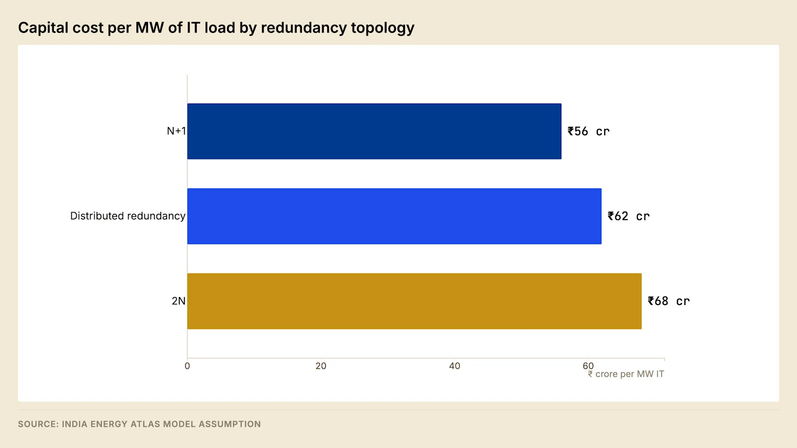
The capital difference between the least and most redundant topology is substantial, and the reduction in expected downtime that it buys is a few hours a year. Valuing that reduction at the service level credits it avoids produces a payback period measured in decades, and an operator running that calculation will conclude that redundancy beyond N+1 is uneconomic.
The calculation is the wrong one. Service level credits are a remedy for a facility that has failed, and they are capped at a fraction of monthly rent. They are not a measure of what fault tolerance is worth, because the tenants who require fault tolerance do not lease facilities that lack it at any price.
The correct measure is tenant addressability. Regulated financial services workloads, a substantial share of government cloud requirements, and much of the hyperscale wholesale market specify fault tolerance as a threshold condition of tender rather than as a preference to be priced. Hyperscale tenants accounted for the substantial majority of Indian absorption in the first half of 2026. A topology that cannot be offered to the segment driving most of the demand does not have an availability problem. It has a vacancy problem, and the ramp analysis in Post 1 establishes what sustained vacancy costs over an asset life.
Distributed redundancy is where most sophisticated Indian designs settle. It delivers fault tolerance at approximately half the capital premium of full 2N, at the cost of an electrical room footprint penalty that is tolerable on a greenfield site and frequently is not on a constrained urban one.
5. Sizing against measured load #
Measured accelerated-computing workload power complicates every capital figure above, in the direction of over-provision rather than under-provision.
Whole-facility simulations built on high-resolution node-level traces indicate that facility power peaks materially below rated design even in periods when node utilisation reaches its maximum, because no benchmarked workload sustains node thermal design power. Real training and inference workloads alternate computation with collective communication and data transfer, and the resulting power trace spends very little time at the top of its range. Under synthetic stress designed to saturate the device, average draw remained below the device rating.
Roughly seventy percent of the electrical and mechanical package scales with peak power rather than with energy consumed. Transformers, switchgear, uninterruptible power supply modules, generators and chillers are all sized against peak. Capital committed to serve a peak that does not occur is capital that earns nothing for the life of the asset.
Design basis | Peak-scaling capex avoided per MW |
Size to 85% of rated IT load | ₹3.91 crore |
Size to 80% of rated IT load | ₹5.21 crore |
Size to 73% of rated IT load | ₹7.03 crore |
This is a measurement finding rather than a licence to undersize. The observed ceilings come from one hardware generation and one benchmark suite, and a tenant deploying a genuinely saturating workload will draw whatever the design permits. The defensible response has three parts: write contractual power caps into leases so that the design basis is enforceable, instrument at block level so that actual peak is known rather than assumed, and design the distribution so that capacity can be added within a block rather than provisioning all of it at commissioning. An operator without block-level measurement has no evidentiary basis on which to claim the headroom.
6. Indian design factors #
Imported design standards assume a temperate ambient, a stable grid and a mature spares supply chain. Five conditions require departure from them, and each changes a quantity rather than a preference.
Ambient derating. A design ambient in the mid to high forties in northern and central India derates diesel generator output materially against ISO standard rating, and derates transformer and switchgear ratings as well. A generator plant sized on nameplate is undersized on the design day. Specifications should state site-rated capacity rather than prime or standby nameplate, and the derating should be applied before the redundancy count is established rather than after. The arithmetic that converts a nameplate rating into a site rating, and the plant sizing that follows from it, is carried out in Post 6.
Harmonic distortion. Indian supply carries higher harmonic content than the standards assume, which affects transformer heating, neutral conductor sizing and the selection of uninterruptible power supply input filters. K-rated or equivalent transformers and oversized neutrals are appropriate rather than optional.
Voltage variation. Wider steady-state voltage variation on the incoming supply requires on-load tap changers on primary transformers and affects the transfer settings on automatic transfer switches. Tap changer duty is correspondingly higher, which is a maintenance consideration rather than a design one.
Humidity and pollution. Coastal sites carry salt-laden humidity and inland industrial sites carry particulate loading, both of which drive enclosure ingress protection ratings, conformal coating on electronics, and the selection between air-insulated and gas-insulated switchgear. Gas-insulated switchgear carries a capital premium and a substantially smaller footprint, which frequently decides the question on urban sites independently of the environmental argument.
Spares and response time. Manufacturer response times and spares availability vary widely by location and by original equipment manufacturer. A redundancy topology is a statement about how long the facility can operate with a component out of service, and it is only valid if the component can be replaced within that period. Critical spares holdings should be specified against actual local response times rather than contractual ones.
6.1 Harmonic sources and the mitigation ladder #
Distortion arises principally inside the facility. The rectifier front end of a server power supply, the input stage of an older uninterruptible power supply, and the variable speed drives on chillers and pumps all draw non-sinusoidal current, and three effects follow. Harmonics at multiples of three add rather than cancel in the neutral of a three-phase four-wire system, so neutral current can exceed phase current. Transformer eddy-current loss rises with the square of the harmonic order, so a transformer carrying distorted current runs hotter at the same apparent load, which is the effect K-rated construction addresses. Power factor correction capacitors resonate with the system inductance, and where the resonant frequency falls near an order present in the load, the capacitor amplifies that order.
Measure | Mechanism |
Active front end on the uninterruptible power supply | Controlled rectifier draws near-sinusoidal input current |
Twelve-pulse rectifier with a phase-shifting transformer | Lower orders cancel by phase displacement |
Delta-star transformer | Triplen harmonics circulate in the delta winding |
Passive tuned filter | Low impedance path presented at one frequency |
Active harmonic filter | Compensating current injected from measurement |
K-rated transformer with enlarged neutral | Heating tolerated rather than the cause removed |
The measurement problem sets the boundary. Distortion in service is produced by tenant equipment the operator does not select, and the load banks used at commissioning are normally resistive and therefore linear, so a survey taken then measures the facility's own contribution and not the condition it will operate in. The survey has to be repeated with tenant equipment installed, at the transformer secondary and at the point of connection.
6.2 Power quality at the rack and its measurement #
The preceding subsection treats the distortion the facility's own load injects into the system. This one treats what the tenant's equipment experiences at its own terminals, which is a different quantity, measured in a different place, and it is the quantity a colocation lease actually commits to.
The measurement point determines what a record can be used to establish. Everything upstream of the rack is transformed, conditioned or both, and the equipment responds to the voltage at its inlet after the voltage drop of the busway run and the final circuit. A facility that instruments the transformer secondary, records a clean supply and offers that record in answer to a tenant's complaint has measured a position that did not fail.
Quantity | Position that has to be instrumented | What it affects at the rack |
Steady-state voltage magnitude | The most remote outlet on the most heavily loaded run | Power supply operating margin, and the current drawn for the same power |
Voltage unbalance between phases | The board and each busway run | Heating in three-phase equipment, and neutral current |
Voltage distortion | The board serving the row | Equipment susceptibility, and heating in shared plant |
Frequency | Any point on the system | Identification of whether the load was on utility, generator or inverter supply |
Sags, swells and interruptions | The board, with an event record | Equipment trips, and the dispute that follows one |
Transients | The board, with a fast transient record | Failures in power supplies and control electronics |
Unbalance is the quantity a facility controls directly and neglects most often. Single-phase rack loads distributed unevenly across the three phases produce it, and the audit that corrects it is the same outlet-level audit the field note in section 2 prescribes for feed assignment, performed at the same time by the same person. The neutral current that unbalance produces adds to the neutral current produced by the harmonic mechanism above, so the two effects have to be assessed on the same measurement rather than separately.
Voltage magnitude at the rack is set by the distribution sizing chain in section 7.1, and the measurement consequence of that chain is specific: the lowest outlet voltage in the hall is at the far end of the most heavily loaded run, so instrumenting the board alone cannot establish the condition at the position most likely to be out of tolerance.
An event record has to satisfy several conditions before it is evidence of anything.
Property of the record | Why it is required |
Measurement class stated, per IEC 61000-4-30 | Instruments of different class report different values for the same event |
Aggregation interval stated | A short disturbance disappears inside a long averaging interval |
Time synchronised to a common clock across systems | A supply event and an equipment trip cannot otherwise be correlated |
Continuous recording rather than a survey after a complaint | The event that matters occurred before the instrument arrived |
Measurement position recorded against the board tag | A value without a position evidences nothing about any position |
The synchronised clock is the condition that decides most tenant disputes. Where the uninterruptible power supply log, the electrical power monitoring system and the tenant's own equipment log run on unsynchronised clocks, a trip and a supply disturbance separated on paper by an unknown offset cannot be shown to be the same event or different ones, and the argument is settled by commercial weight rather than by evidence. The scope boundary between an energy monitoring system and a power quality instrument, which sample different quantities at different rates for different purposes, is set out in Post 9.
The diligence question follows from the table. A lease that commits to a supply envelope without naming the measurement position, the measurement class and the aggregation interval has committed to a quantity neither party can compute, and the first disturbance that reaches a tenant's equipment converts that omission into a negotiation.
7. Density and its electrical consequences #
High-density racks change the electrical design before they change the cooling design, and the sequence is frequently misunderstood.
Increasing rack density raises the current carried by the busway serving the rack row, which changes busway rating, tap-off box selection and the short-circuit withstand requirement on the downstream distribution. It raises the fault level at the rack, which affects protective device coordination. It concentrates load, so a smaller number of distribution failures affect a larger share of the facility, which reduces the effective fault domain unless the distribution is subdivided further.
A facility designed for conventional enterprise densities and subsequently populated with accelerated computing equipment will encounter its electrical limits before its thermal limits, typically at the busway and at the secondary distribution. Retrofitting the distribution inside an operating hall is possible and expensive, and it requires outage windows that tenants with continuous operations will not grant. Designing the distribution for a higher density than the initial tenant requires, and populating it progressively, is materially cheaper than the retrofit.
7.1 Current, voltage drop and the distribution sizing chain #
The mechanism behind the density constraint is arithmetic rather than thermal. Conductor loss rises with the square of current, so doubling the density of a row quadruples the loss in the conductor serving it unless the conductor is enlarged, and that loss falls into the facility's own consumption rather than the tenant's metered draw. Voltage drop rises in proportion to current and to length, so beyond a certain run length the conductor is sized by voltage drop rather than by its thermal rating, which is why the position of the electrical room is a density decision.
Step | Quantity fixed | Governed by |
1 | Rack power at the outlet | Tenant equipment and the contractual cap |
2 | Circuit current | Rack power, distribution voltage, phase configuration |
3 | Tap-off box and final circuit rating | Circuit current with derating applied |
4 | Busway or feeder rating | Sum across the row, diversity stated |
5 | Panel and breaker frame size | Feeder rating and prospective fault current |
6 | Secondary transformer rating | Sum of the boards it serves |
7 | Prospective fault current at each board | Transformer impedance and bus configuration |
8 | Protective device selection and settings | Fault current and the grading scheme |
A change at the first step propagates to the last, which is why density is fixed before long-lead procurement rather than during fit-out.
8. Commissioning and the proof of a topology claim #
A topology claim states that the facility will behave in a defined way under a defined set of failures, and the only evidence for it is a test in which those failures were induced and the behaviour observed. Commissioning proceeds in stages that differ in what they prove.
Stage | What it proves | What remains unproven |
Factory acceptance testing | The unit meets its specification in the factory | Anything about the installation |
Pre-functional checks | Connections, settings, protection values, insulation | Behaviour under load |
Functional performance testing | Each system operates correctly in isolation, at load | Interaction between systems |
Integrated systems testing | Systems operate together at design load, with transfer and restoration | Behaviour on a single failure, unless scripted |
Failure-mode testing | Each single failure the topology claims to survive | Combinations not scripted, behaviour after modification |
The last row carries the claim, and it is the row most often reduced under schedule pressure. Failure-mode testing requires the facility to be driven into a condition in which something is deliberately broken, on load banks, at design load, with the plant new. It carries a risk of damaging equipment, it consumes time available only at the end of a programme that has usually slipped, and its output is a document rather than a milestone. A facility entering service without it holds an untested claim, and the first genuine single failure performs the test with tenants connected.
The script is the document to ask for rather than the certificate. It enumerates every point whose failure the design claims to survive and states, for each, the method of inducing it, the expected behaviour, the quantity measured, and the acceptance criterion. Where the claim is fault tolerance, the enumeration covers the utility incomer, each transformer, each generator, each uninterruptible power supply module, each transfer device, each bus section and each distribution path, in both bus configurations and on both sources.
The black building test is the most informative single test in the sequence. The incoming supply is opened with the facility at load, and the sequence that follows covers stored energy carrying the load, generator start and load acceptance, plant restart in its designed order, and the return to utility supply. In a block architecture it can be repeated on one block while the others carry tenants.
Document | What makes it stale |
As-built single-line diagrams | Any modification to the distribution |
Short-circuit study | A transformer, generator or source change |
Coordination study and settings file | Any device or setting change |
Arc-flash study and equipment labels | A change to protection settings or arrangement |
Earthing and bonding records | Elapsed time, excavation, any fit-out |
Failure-mode script and results | Any modification to plant or sequencing |
An acquirer should request that set and read the dates before the conclusions, because a coordination study predating the last transformer replacement, or a script with tests marked deferred, identifies a respect in which the facility in service differs from the specification. The remedy in each case is a test rather than a document, and running it on an occupied facility costs what the original programme avoided.
8.1 The failure-mode test matrix #
The script described above is an enumeration, and its usable form is a matrix with one row per claim. Each row carries the claim, the failure induced to test it, the observation that decides the result, and the criterion against which that observation is judged. A row without all four is an intention rather than a test, and a script consisting of intentions is what produces a commissioning report in which every line reads satisfactory and nothing was measured.
Claim under test | Failure induced | What is observed | Acceptance |
Two independent incoming sources | One incomer opened at load | Load remains supported from the second source | No interruption at the outlet, and no transfer of critical load to stored energy |
Primary transformation redundancy | One power transformer removed from service at load | Remaining transformation carries the load | Load carried within rating, with no thermal alarm |
Medium voltage bus redundancy | One bus section de-energised | The remaining section and the tie behave as designed | Transfer completes inside the interval the design states |
Standby generation redundancy | One set inhibited from starting | The remaining sets accept the load | Load accepted, with voltage and frequency recovering inside the design envelope |
Transfer scheme operation | Incoming supply opened at load | The transfer sequence executes in its designed order | Sequence recorded, each step inside its stated interval |
Stored energy autonomy | Supply opened with generator starting inhibited | The inverter holds the load to the design autonomy | Autonomy achieved at design load, with end voltage reached no earlier |
Module redundancy in the uninterruptible power supply | One module removed from service at load | Remaining modules carry the load | No transfer to static bypass at any point |
System redundancy in the uninterruptible power supply | One complete system de-energised | The alternate system carries the whole load | No interruption at the outlet on either cord |
Static transfer switch operation | Preferred source removed from the switch | Transfer completes within its stated time | Load unaffected, and the register of single-corded positions verified against the field |
Distribution path redundancy | One busway run or one riser de-energised | Racks remain fed on the alternate path | No load lost, and the feed assignment audit reconciles |
Control power availability | One direct current supply removed | Protection and tripping remain available | Trip circuit supervision healthy throughout the test |
Independence from the monitoring system | Control and monitoring taken out of service | Plant continues in its designed state without it | No change of state, and no loss of protection function |
Four conditions decide whether a row's result is evidence. The test is performed at design load rather than at whatever load is available, because the behaviour that matters is the behaviour under the duty the claim covers. The plant is in its normal configuration rather than a configuration arranged for the test, since a tie closed for convenience turns a fault-tolerance test into a demonstration of a system that will not exist in service. The sequence of events is captured on a time-synchronised record, because the acceptance criterion for most of these rows is an interval rather than a state. The test is repeated in the alternate bus configuration and on the alternate source, since a facility that has proven a claim on one side has proven half of it.
Load bank position is the condition that separates an electrical proof from a facility proof. Load banks connected at the low voltage board exercise the electrical chain from the source to that board and nothing below it, so a test arranged that way leaves the busway, the tap-off boxes and the rack distribution untested at load, and it establishes nothing at all about airflow or the hall's behaviour when heat rejection stops. Load in the hall at rack positions is what tests the distribution as installed, and the thermal ride-through that runs alongside it belongs to the cooling design in Post 5.
The record has to be written for a reader who was not present. For each row it states the date, the configuration at the start, the method of inducing the failure, the instrument used, the measured values with their timestamps, the result against the criterion, and the disposition of any deviation. A row marked as passed without the measured value is not recoverable later, and it is the row a subsequent acquirer will ask about.
Re-testing is triggered by modification rather than by the calendar, with the same trigger list that makes the studies stale. The practical arrangement is to name the failure-mode script in the change control process, so that a plant change raises the affected rows for re-test as part of the change itself; the change control mechanism this attaches to is described in Post 9. A subset re-run on a defined cycle covers the slow failures that no modification triggers, and in a block architecture that subset can be executed on one block while the others carry tenants, which is the operational return on the fault domain decision in section 3.
Forward look #
Two developments over the next eighteen months would change the topology calculation.
The first is the price and availability of lithium uninterruptible power supply systems. Lithium reduces the footprint and extends the replacement interval relative to valve-regulated lead acid, and as the price differential narrows the distributed redundancy topology becomes cheaper to implement in a constrained electrical room.
The second is whether tenants begin to accept contractual power caps as standard. If they do, the measured-load finding in section 5 becomes bankable and design bases can be reduced with lender support. If they do not, the capital committed to peaks that do not occur remains in every project in the sector.
FAQ #
What is the difference between concurrent maintainability and fault tolerance? Concurrent maintainability means any component can be removed for planned maintenance with the load supported. Fault tolerance means an unplanned single failure does not affect the load. The second is the stronger condition, because a fault occurs in whatever configuration exists at the time.
How much more does 2N cost than N+1? On the model in section 4, the difference is roughly a fifth of capital cost per MW of IT load, together with a substantially larger electrical room footprint. Distributed redundancy delivers fault tolerance at approximately half that premium.
Should redundancy be justified by the service level credits it avoids? No. Credits are capped remedies for a facility that has already failed. The determining consideration is which tenants will lease the facility, because fault tolerance is a threshold condition of tender for regulated and hyperscale workloads rather than a priced preference.
What is a fault domain and why does it matter? The quantity of load affected by a single fault. It is set by how the facility is divided electrically, not by the redundancy notation, and dividing a facility into blocks reduces it while also permitting capital to be phased against the occupancy ramp.
Which Indian conditions require departure from imported design standards? Ambient derating of generation and transformation, higher harmonic content, wider voltage variation, humidity and pollution driving enclosure and switchgear selection, and local spares response times that determine whether a redundancy claim is operationally valid.
What evidence supports a fault tolerance claim? A failure-mode test script that enumerates every point whose failure the design claims to survive, with the method of inducing each failure, the expected behaviour and the measured acceptance criterion, together with the recorded results. A certificate without the underlying script does not identify which failures were tested and which were deferred.
Sources #
Uptime Institute, Tier Standard: Topology, and Tier Standard: Operational Sustainability
CEA, Technical Standards for Connectivity to the Grid Regulations
Vercellino et al., measured GenAI workload power traces, arXiv:2604.07345, April 2026
Savills India, India Data Centre Market Update H1 2026, July 2026
India Data Centre Review 2026 (v2.3, edition cutoff 28 July 2026), Chapter 5 — India Energy Atlas
Engineering standards named as governing instruments in the text, with no clause, limit or class threshold taken from any of them:
IEC 60617, graphical symbols for diagrams — section 1.3
IEC 62271, high-voltage switchgear and controlgear — section 2.4
IEC 61439, low-voltage switchgear and controlgear assemblies — section 2.4
IEC 61000-4-30, testing and measurement techniques for power quality measurement methods — section 6.2
Topology capital costs, the downtime estimates, the footprint index and the avoided-capex table are modelled by India Energy Atlas and are labelled as model assumptions. The comparison tables covering drawing contents, switchgear media and pattern, transfer schemes, paralleling, direct current systems, stored energy sizing, rotary alternatives, transformer media, protection grading, fault level, neutral earthing, earth fault measurement, the coordination study, arc flash, earthing, harmonic mitigation, power quality records and commissioning state general engineering practice and are not attributable to an external source. Where a standard would supply a numeric limit, the text states the mechanism and the verification method instead of the value. IDCR 2026 figures are quoted at the locked edition snapshot of 13 July 2026; live Atlas products may carry newer records.
This post was revised against the measured GenAI load-profile analysis — see the working note for the load derivation, ramp rates and the peak-to-nameplate ceiling.
Read the full series — The Indian Data Centre Playbook, twelve parts from unit economics to exit.
Next in the series — Part 5: Cooling in an Indian Climate. Holding design PUE across four climate zones, and the water consequences of each cooling architecture.
India Energy Atlas builds India's grid intelligence layer. See energymap.in/pricing.
Sources & method
- Uptime Institute, Tier Standard: Topology, and Tier Standard: Operational Sustainability - CEA, Technical Standards for Connectivity to the Grid Regulations - Vercellino et al., measured GenAI workload power traces, arXiv:2604.07345, April 2026 - Savills India, India Data Centre Market Update H1 2026, July 2026 - India Data Centre Review 2026 (v2.3, edition cutoff 28 July 2026), Chapter 5 — India Energy Atlas Engineering standards named as governing instruments in the text, with no clause, limit or class threshold taken from any of them: - IEC 60617, graphical symbols for diagrams — section 1.3 - IEC 62271, high-voltage switchgear and controlgear — section 2.4 - IEC 61439, low-voltage switchgear and controlgear assemblies — section 2.4 - IEC 61000-4-30, testing and measurement techniques for power quality measurement methods — section 6.2 Topology capital costs, the downtime estimates, the footprint index and the avoided-capex table are modelled by India Energy Atlas and are labelled as model assumptions. The comparison tables covering drawing contents, switchgear media and pattern, transfer schemes, paralleling, direct current systems, stored energy sizing, rotary alternatives, transformer media, protection grading, fault level, neutral earthing, earth fault measurement, the coordination study, arc flash, earthing, harmonic mitigation, power quality records and commissioning state general engineering practice and are not attributable to an external source. Where a standard would supply a numeric limit, the text states the mechanism and the verification method instead of the value. IDCR 2026 figures are quoted at the locked edition snapshot of 13 July 2026; live Atlas products may carry newer records. Photography: - Photo by Troy Bridges on Unsplash (https://unsplash.com/photos/gray-power-switch-box-maXnRLszYY0?utm_source=india_energy_atlas&utm_medium=referral) - Photo by Troy Bridges on Unsplash (https://unsplash.com/photos/black-machine-nt5Tjdg-9ks?utm_source=india_energy_atlas&utm_medium=referral)