

Operating an Indian Data Centre: The Gap Between Design and Delivered Efficiency
Why Indian data centres operate above their design PUE, the mechanisms that open the gap, what recovering it is worth, why the lease structure determines who captures that value, and the metering and SLA architecture required to govern it.
The short answer. Indian data centres routinely operate above their design power usage effectiveness, and the gap is recoverable. Half the interventions that recover it require no capital expenditure. Under a standard cost pass-through lease the operator funds the recovery and the tenant captures the benefit, which is the reason the gap persists.
This post sets out why delivered efficiency differs from design efficiency in Indian data centres, the mechanisms that produce the difference, what closing it is worth, why the commercial structure determines whether anyone acts, and the metering and contractual architecture required to govern performance at all.
It is written for the operator accountable for annualised performance, the asset manager assessing whether an operating facility is being run well, and the tenant negotiating a performance clause.
The gap between design and delivered efficiency is not a failure of engineering. Every mechanism described below is the result of a reasonable decision taken by somebody who was not accountable for annualised performance, which makes the problem organisational and contractual before it is technical.
1. The mechanisms #
Mechanism | What occurs | Typical effect on PUE |
Part-load operation | Plant sized for full build-out runs at a fraction of that load through the occupancy ramp | +0.04 to +0.08 |
Setpoint drift | Chilled water supply left at the original design value as the load population changes | +0.03 to +0.06 |
Containment decay | Blanking panels and floor grommets removed during rack installation and not restored | +0.02 to +0.04 |
Tenant inlet specification | Lease specifies a narrower temperature band than the installed equipment requires | +0.01 to +0.03 |
Commissioning gaps | Control sequences never fully tuned, so modelled economiser hours are not realised | +0.02 to +0.05 |
Part-load operation is the largest and the least avoidable. A chilled water plant sized for the full build-out operates at its worst efficiency point when the hall is a third occupied, and that condition coincides with the years in which the asset is already earning below its cost of capital, as set out in Post 1. Staging the plant to match the ramp addresses it, and staging requires a design decision taken before construction rather than an operational one taken afterwards.
Setpoint drift describes a plant that continues to operate at the chilled water temperature specified for its original design population after that population has changed. Modern equipment tolerates considerably higher inlet temperatures than legacy equipment, and every degree of supply temperature increase improves chiller efficiency and increases the hours in which economiser operation is available. The obstacle is that no individual is usually accountable for the setpoint: raising it presents as a risk taken by a named person, and leaving it presents as nothing at all.
Containment decay is continuous rather than episodic. Blanking panels are removed to install a rack and are not replaced. Floor grommets are opened to route a cable and are not resealed. Each instance is trivial and the cumulative effect is recirculation of hot air into the cold aisle, which raises the supply temperature required and destroys more efficiency than equipment selection recovers.
Tenant inlet specification is a contractual mechanism rather than a technical one. Where the lease specifies an inlet temperature band narrower than ASHRAE allowable conditions for the equipment installed, the operator is contractually prevented from exercising the largest available lever. This is negotiable at lease renewal and is rarely raised.
Commissioning gaps arise because integrated systems testing verifies that the plant meets its design condition and rarely verifies that its control sequences behave correctly across the full range of ambient conditions. Economiser changeover logic in particular is frequently left at its default, so the free cooling hours in the design model are not realised in operation.
1.1 Origin and timing of each mechanism #
The five mechanisms surface at different points, and the party able to prevent each has usually left the project before it becomes visible.
Mechanism | Decision that creates it, and who takes it | Stage at which it surfaces |
Part-load operation | Plant staging fixed at detailed design | First operating year, at low occupancy |
Setpoint drift | Commissioned value left unchanged by the commissioning agent | When the equipment population changes |
Containment decay | Rack and cabling works by contractors and tenant staff | Continuously, as a widening inlet temperature spread |
Tenant inlet specification | Band agreed by the commercial team without thermal input | When a setpoint change is proposed |
Commissioning gaps | Scope and season of integrated systems testing | At the first seasonal extreme after handover |
Each party in the second column is accountable for a different deliverable and none for annualised efficiency, and the operations team inheriting all five decisions holds no authority to reverse them. The diligence question therefore concerns authority: who may change a chilled water setpoint, and when one was last changed.
1.2 The commissioning-to-operations handover #
Commissioning establishes that the plant meets its design condition. Operation requires knowledge of how it behaves across every condition it will meet, and the documentation to change that behaviour safely.
Handover artefact | What it must contain | Consequence of its absence |
Sequence of operations | Every control action, its trigger, setpoint, interlocks and range | Controls cannot be retuned without reverse-engineering the logic |
Commissioning record by level | Factory, site acceptance, functional and integrated results | Untested modes surface as failures rather than as findings |
Setpoint register | Each setpoint, its commissioned value, range and authorised owner | Drift cannot be detected, because no reference exists |
Alarm database | Each alarm point with cause, priority and required response | Triage falls on the shift engineer unaided |
As-built drawing set | Diagrams and schematics as installed rather than as designed | Isolation is planned against a drawing that is wrong |
The gap that matters most is seasonal. A facility commissioned in one part of the year has never been observed at the opposite extreme, so its economiser changeover logic remains unverified until the following season, by which time the contractor has demobilised. Both remedies belong in the construction contract: a seasonal commissioning obligation, and a retention held against that visit rather than against practical completion.
1.3 Operational readiness before handover #
Construction delivers a facility that works. Operational readiness delivers an organisation able to run it, and the two programmes have different owners, different deliverables and different critical paths. Readiness is treated as an event at handover on most Indian projects, which is the reason the first operating year carries defects created during construction and discovered by a shift team recruited after the contractor demobilised.
Readiness workstream | Deliverable required at first live load | Construction output it depends on |
People | Shift teams recruited, inducted and authorised on this plant | Access to the plant while it is being commissioned |
Procedures | Standard, emergency and method-of-procedure library written against the as-built | As-built drawings and the sequence of operations |
Systems | Asset register loaded, alarm database rationalised, monitoring points named and mapped | Installed asset list and the point schedule |
Materials | Critical spares on site, consumables stocked, test equipment calibrated | Vendor spares lists and the commissioning parts record |
Contracts | Vendor maintenance agreements executed, with response obligations running | Equipment schedules and confirmed warranty start dates |
Governance | Permit-to-work regime live, authorisation matrix signed, escalation tree tested | None; this workstream can close early |
Five of the six workstreams depend on a construction output, and each of those outputs is produced late in the programme because it describes the facility as finally built. Readiness therefore compresses into the weeks in which the project is also completing its own tests, and the workstream with no construction dependency is the one most often left until last. The remedy is to sequence each readiness deliverable against the construction milestone that releases it, and to make the deliverables conditions precedent to handover rather than actions following it.
The cheapest training available to an operations team is attendance at integrated systems testing. Those tests deliberately fail the plant and observe what the design does about it, which is the only occasion on which the failure behaviour of the facility is produced under controlled conditions with the designers present. A shift engineer who has watched the facility lose its incoming supply on a scheduled test has seen the sequence once. A shift engineer recruited after handover sees it first during an event.
Readiness defect | How it presents in the first operating year |
Team recruited after commissioning | Plant behaviour under fault is unknown to the people required to act on it |
Procedures written from vendor manuals | Steps refer to equipment that was substituted, or arranged differently on site |
Register loaded from the procurement schedule | The maintenance plan addresses equipment that is not installed |
Spares ordered after handover | The first failure inside the warranty period runs without a part |
Vendor agreements signed after energisation | The warranty period elapses with no maintenance performed under it |
Authorisation matrix incomplete | High voltage switching depends on contractor staff after demobilisation |
Occupation is staged, so readiness is tested twice. The first test is at first live load, when a single hall carries a fraction of its design load and the plant is at its least efficient operating point. The second is at the first significant load, which is the first condition under which a failure has a consequence. A readiness review repeated at that second point, against the same workstreams, catches the items that were signed off on a promise.
The diligence request is the operational readiness plan with the closure date recorded against each workstream, set beside the date of first live load. A satisfactory response shows the closures preceding the load rather than following it, and names the individual who accepted each workstream on behalf of operations.
2. The value of recovery #
Model assumption — recovery interventions on a 20 MW IT block at 85% utilisation, ₹7.50 per unit
Intervention | Effect on PUE | Annual energy saved (MWh) | Annual value | Capital required |
Raise chilled water supply temperature within ASHRAE allowable | −0.050 | 7,446 | ₹5.58 crore | None — controls and commissioning |
Restore and maintain containment integrity | −0.030 | 4,468 | ₹3.35 crore | Minimal — panels and grommets |
Variable speed drive retrofit and pump-fan optimisation | −0.020 | 2,978 | ₹2.23 crore | ₹4–6 crore |
Widen tenant inlet band to ASHRAE allowable | −0.020 | 2,978 | ₹2.23 crore | None — lease negotiation |
Stage plant to match actual load | −0.015 | 2,234 | ₹1.68 crore | Controls logic and sequencing |
UPS module right-sizing and eco-mode where permitted | −0.010 | 1,489 | ₹1.12 crore | ₹2–4 crore |
Total | −0.145 | 21,593 | ₹16.19 crore | ₹8–12 crore |
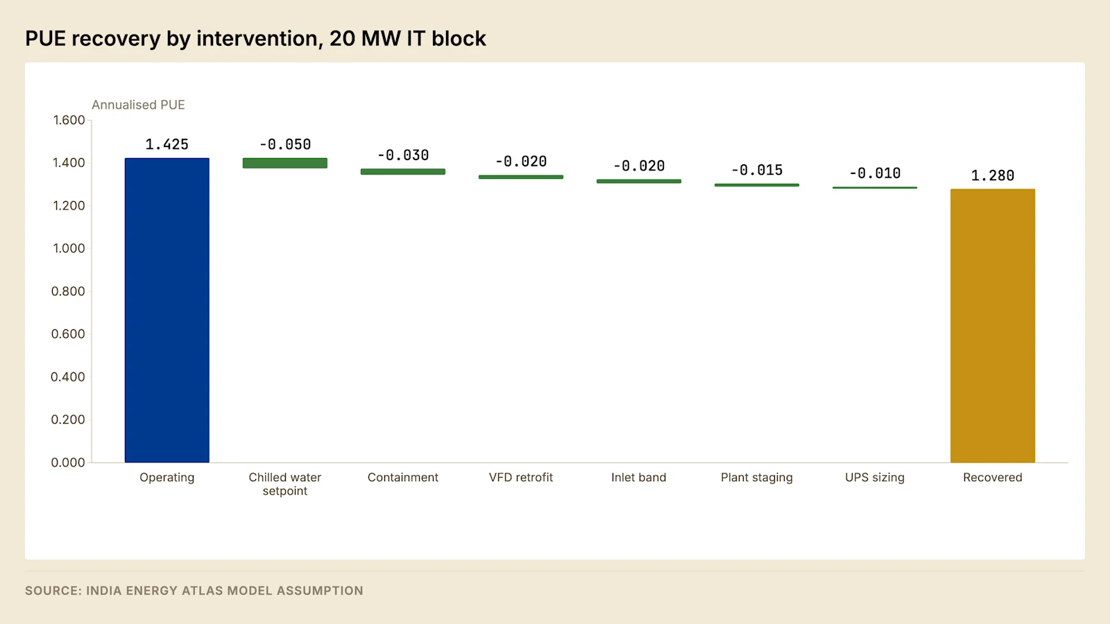
Three of the six interventions require no capital. They require a controls engineer with a mandate, a commissioning report that somebody reads, and a conversation with the tenant about inlet temperature bands.
The benchmark against which a facility should be assessed is its class rather than an absolute target, because vintage and design intent bound what is achievable.
Facility class | India, installed base | India, new builds | Global best-in-class |
Legacy colocation, pre-2020 | 1.6–1.8 | — | — |
Modern colocation, 2020–25 | 1.4–1.6 | 1.35–1.45 | 1.2–1.3 |
Hyperscale captive | 1.25–1.4 | 1.2–1.3 | 1.08–1.12 |
High-density AI and HPC | — | 1.15–1.25 | 1.06–1.1 |
Source: IDCR 2026, Chapter 5.
Part of the gap between Indian and best-in-class performance is climate and is not recoverable by operation, as set out in Post 5. The remainder is the operating gap this post addresses, and it is the part that responds to a controls engineer.
At national scale the same gap is a policy variable. Moving the Indian operating fleet to the target average across the capacity expected by 2030 saves energy on the order of tens of terawatt-hours annually, and a national PUE standard is in consultation.
2.1 Dependency order of the interventions #
The interventions above are not independent, and the wrong order produces a failed programme rather than a smaller saving.
Order | Intervention | Precondition |
First | Metering to the depth the measurement category requires | None |
Second | Inlet temperature survey and containment restoration | Metering, so effects can be attributed |
Third | Chilled water supply temperature raised in stages | Containment integrity and headroom at the worst rack |
Fourth | Plant staging and sequencing logic | A load profile across a full season |
Fifth | Variable speed drive retrofit and pump-fan optimisation | Control strategy settled |
Sixth | Tenant inlet band renegotiation | Measured evidence from the preceding steps |
The constraint on the third step is the least favourable rack rather than the hall average, and that position is set by recirculation and blanking panel discipline rather than by the plant; the physics is set out in Post 5. Where the order is reversed, supply temperature rises into a hall with unrestored containment, one rack alarms, and the change is reversed under tenant pressure with a durable loss of appetite for repeating it.
2.2 Measurement and verification of a claimed recovery #
An improvement claimed without a stated verification method cannot be relied on, because the largest confounding variable moves in the same direction as the intervention: occupancy rises over the period of the work, the part-load penalty falls as it rises, and annualised efficiency improves for reasons unconnected to any controls change.
Element of the protocol | What it must state | Failure mode if omitted |
Baseline period | Calendar period, IT load range and ambient conditions | A baseline drawn from an unrepresentative season |
Normalisation basis | Adjustment for IT load, occupancy and ambient wet bulb | The occupancy ramp reported as an efficiency gain |
Measurement category | The category, and the meters supplying each term | The two terms measured on different bases |
Averaging period | Annualised, or a shorter window with the reason stated | A favourable month reported as an annual result |
Exclusions | Treatment of outages, generator running, partial occupancy | An excluded period conceals the effect measured |
Verification party | Who computes the result, and what access it holds | Neither side accepts the other's calculation |
The normalisation basis is what disputes turn on, because it is the only element requiring judgement: adjusting for IT load is arithmetic, while adjusting for ambient conditions requires a model relating plant power to wet bulb, built from the facility's own trend data.
The analysis stops holding in three conditions: a hall converted to direct liquid cooling; a facility already close to its design efficiency, where the capital-free recovery is exhausted; and a design figure derived from a wet-bulb condition imported from another market.
2.3 Benchmarking against peers and the limits of the comparison #
A reported efficiency figure is a ratio of two measured quantities computed under a stated method, so two figures compare only where the method and the operating conditions agree. Six terms have to agree before a peer comparison carries information, and in Indian practice most of them are undisclosed.
Term | Why it moves the figure | What to obtain before comparing |
Measurement category | Moves the denominator, so the ratio moves arithmetically | The declared category under ISO/IEC 30134-2 |
Facility boundary | Fixes which shared and ancillary loads sit inside the numerator | The boundary statement and the campus arrangement |
Averaging period | A design-day or best-month figure is not an annual figure | Start and end dates spanning a full year |
Climate | Wet bulb bounds heat rejection, and that component is not recoverable by operation | The location and the design condition |
Occupancy and load factor | Part-load operation raises the ratio while a hall is filling | IT load as a proportion of design load over the period |
Design intent and density | A hall built for one density operates away from its best point at another | Design density against installed density |
The climate term is treated in Post 5, which owns the physics and the city-by-city annualised figures for a single design. The occupancy term is the mechanism in section 1, and the category term is the arithmetic in section 4.1.
The comparison that always carries information is a facility against its own history on an unchanged method, because five of the six terms are held constant by construction. That comparison is available to every operator and requires no disclosure by anybody else, which makes the absence of a trended internal series the more informative finding when a facility cannot produce one.
Peer benchmarking in India is bounded by disclosure rather than by method. Most operators are unlisted, and those that report do so at corporate rather than facility level, so the published population is small and its members are not drawn at random from the fleet. The reporting instrument is the Business Responsibility and Sustainability Reporting requirement, which binds listed entities and produces aggregated figures across a corporate group rather than a figure attributable to a building.
Use of a peer figure | Whether it holds |
Allocating diligence effort across a portfolio | Yes, at class level |
Setting an internal improvement target | Yes, with class and climate stated alongside it |
Testing whether a claimed figure is plausible | Yes, against the class band |
Fixing a contractual baseline | No; the method behind the peer figure is not available |
Establishing that an operator is competent | No; vintage and design intent bound what operation can reach |
The fourth row is the one that costs money. A baseline drawn from a peer figure imports that peer's category, boundary, climate and occupancy, none of which is stated, and binds the operator to a number produced under conditions it does not share. Baselines are measured on the facility they bind, over a period named in the clause, on the metering that will be used to report against them.
3. Who captures the value #
The interventions in section 2 cost money and save money, and under most Indian lease structures the two accrue to different parties.
Lease structure | Who funds recovery | Who receives the saving | Operator incentive |
Wholesale, energy at landed cost | Operator | Tenant | None |
Wholesale with PUE cap | Operator | Operator above the cap, tenant below | Partial, to the cap |
Wholesale with gain share | Operator | Split as drafted | Aligned |
Retail colocation, bundled energy | Operator | Operator | Full |
Under a cost pass-through lease the operator bills energy at landed cost. Reducing PUE reduces the quantity of energy billed, which reduces the tenant's payment and leaves the operator's revenue unchanged. The operator has funded an improvement in somebody else's cost base, and no rational operator does that twice.
This is the reason Indian facilities operate above their design efficiency. It is not an engineering failure and it is not addressed by engineering. It is addressed in the lease, through one of three drafting devices.
A PUE cap sets a threshold above which the operator bears the excess energy cost. It protects the tenant against operational neglect and gives the operator an incentive to remain below the cap, but none to improve beyond it.
A gain share splits the saving from any improvement below an agreed baseline. It aligns both parties and requires an agreed measurement methodology, which is why it appears mainly in leases where metering is already adequate.
A capital contribution has the tenant fund the intervention and retain the whole saving. It is the cleanest structure where the tenant has the balance sheet and the technical capability to specify the work.
Field note. A PUE cap without a stated measurement methodology is unenforceable in practice. The cap has to specify the measurement category under ISO/IEC 30134-2, the averaging period, the metering boundary, and the treatment of partial occupancy. A facility one-third occupied will exceed any cap calibrated on stabilised operation, and a cap drafted without a ramp provision transfers the cost of the ramp to the operator.
3.1 Components of a gain-share clause #
A gain share is the only device that rewards improvement beyond a threshold, and it is the one most often drafted so loosely that it cannot be operated.
Component | What the clause fixes | Consequence if left open |
Baseline | The efficiency measured against, and the period establishing it | Each party proposes the baseline favourable to itself |
Category and boundary | Measurement category, metering points, shared plant treatment | Improvement becomes arithmetic rather than physical |
Normalisation | Adjustment for IT load, occupancy and ambient conditions | The occupancy ramp is billed as an efficiency gain |
Share and ceiling | Proportion accruing to each party, and any aggregate cap | The operator cannot construct an investment case |
Term of the share | Period over which the operator receives its share | A short term does not repay a capital intervention |
Capital treatment | Whether capital is recovered before sharing begins | Capital interventions are never proposed |
Reset mechanism | Whether the baseline resets, and on what trigger | Improvement paid for indefinitely, or the gain penalised |
Audit and dispute route | Audit rights, data access and expert determination | Disputes escalate to the lease as a whole |
The reset mechanism is most often omitted and determines whether the clause survives its second cycle. A baseline that never resets pays the operator in perpetuity for work done once, and a baseline resetting every measurement year removes the incentive, because the share expires before the intervention has repaid its capital.
Field note. Cap and gain-share provisions are frequently drafted against a design PUE stated in an appendix to the lease. A design figure is a modelled value at full occupancy rather than a measurement, so a clause referencing it transfers the whole ramp penalty to the operator. The baseline should be a measured period beginning once occupancy passes a stated threshold.
4. Metering #
Performance cannot be governed without measurement, and the metering hierarchy required is deeper than most Indian facilities install.
Level | Measurement point | What it enables |
1 | Utility revenue meter at the connection | Billing, sanctioned demand monitoring, PUE numerator |
2 | UPS output, mechanical plant, house load, separately | Attribution of the non-IT load, PUE by category |
3 | Power distribution unit or busway tap-off | Per-hall and per-tenant consumption, PUE denominator |
4 | Rack outlet | Per-rack density, stranded capacity, contractual cap enforcement |
Most Indian facilities meter reliably at Level 1 and partially at Level 2. Without Level 3 the denominator of the PUE calculation is estimated rather than measured, which means the reported figure carries an error of unknown sign and the interventions in section 2 cannot be verified. Without Level 4 a contractual power cap cannot be enforced and stranded capacity cannot be identified.
The measurement category matters as much as the metering depth. ISO/IEC 30134-2 defines categories that differ in where the IT load is measured, and a PUE quoted under one category is not comparable to a PUE quoted under another. A facility reporting a favourable figure should be asked which category it used and over what averaging period, and a design-day figure should never be compared with an annualised one.
Interval data at hourly resolution or finer is a separate requirement, and it is increasingly load-bearing. It is required for the hourly carbon matching examined in Post 8, for the deviation settlement management examined in Post 7, and for any participation in the grid services examined in Post 10. A facility installing metering solely to report PUE is installing it for the least valuable of its four uses.
4.1 The measurement categories of ISO/IEC 30134-2 #
The governing standard fixes where IT energy is measured, where total facility energy is measured, and over what period both are accumulated. The categories differ in the first, moving the measurement point progressively closer to the computing equipment.
Category | IT energy measured at | Losses inside the denominator | Reported PUE |
Category 1 | Uninterruptible power supply output | Distribution, busway and rack cabling | Lowest of the three |
Category 2 | Power distribution unit output | Busway and rack cabling | Intermediate |
Category 3 | IT equipment input at the rack | None | Highest of the three |
The fourth column is arithmetic rather than physical. Total facility energy is the same in all three cases, and measuring IT energy further downstream removes distribution losses from the denominator while leaving them in the numerator, so the ratio rises.
Reporting requirement | What it means in practice |
Energy rather than power | Accumulated kilowatt-hours, not an instantaneous or design-day ratio |
Continuous measurement | A record spanning the period, with any sampling basis declared |
Annual reporting period | A full year, so seasonal variation sits inside the result |
Defined facility boundary | Which ancillary loads are included: offices, lighting, shared plant |
Declared substitutions | Any value calculated rather than metered, with its basis |
The boundary requirement produces most of the disagreement on Indian campuses, because shared plant, security and administrative accommodation must be apportioned across buildings let at different densities. A satisfactory answer names the category and its meters, gives dates spanning a full year, identifies values calculated rather than metered, and states where the boundary was drawn.
4.2 Scope boundaries of BMS, EPMS and DCIM #
Three monitoring systems are procured separately, and the boundaries between them determine whether the facility can explain its own performance.
System | Scope | Primary function |
Building management system | Chillers, pumps, cooling towers, CRAH and air handling units, ventilation, life safety interfaces | Closed-loop control of the mechanical plant |
Electrical power monitoring system | Incoming supply, transformers, generators, switchgear, UPS modules, distribution boards | Measurement, protection status, event and waveform capture |
Data centre infrastructure management | White space assets, rack elevations, capacity by position, connectivity, change history | Capacity, asset and change management |
The first two speak BACnet and Modbus, with IEC 61850 at the high voltage interface where the relays support it. The control action sits in the building management system and its energy consequence in the power monitoring system, so neither holds both cause and effect. Unless both feed a common historian on a common time base, the operator cannot demonstrate that a setpoint change produced a saving, which is what a gain-share clause requires.
The pattern is structural: three contractors supply three systems, and integration sits in nobody's scope unless written into one of them. Settle before award which package carries it, against which point list, and with what acceptance test.
4.3 The integration scope of a DCIM deployment #
An infrastructure management platform should be procured against the outputs it must produce: the verification in section 2, the enforcement in section 5, the capacity decisions below, and the external uses in section 7.
Layer | Contents | What degrades it |
Asset and connectivity register | Racks, devices, circuits, ports, patch records and their relationships | A physical change made without a record change |
Capacity model | Power, cooling, space, structural and connectivity capacity per position | Design values used where measured values exist |
Acquisition and historian | Polling of circuit meters, UPS and PDU outputs, plant and sensors | Point naming inconsistent across halls or systems |
Workflow | Change requests, work orders, capacity reservations, permits | A parallel process that bypasses the platform |
Reporting | Efficiency by category, capacity by hall, cap compliance, alarms | A denominator estimated rather than measured |
Deployments fail for the same reason in almost every case, and the reason is data discipline rather than software. The register is accurate on the day it is loaded and degrades from the first change made outside the workflow, after which the capacity model is wrong and the operator returns to a spreadsheet. The remedy belongs in the operating procedures: no rack position is energised without a work order raised in the platform, and the record closes only on physical verification.
Retention is specified against the same outputs: a full year of interval data for verification, sub-minute resolution for incident investigation, and several years of hourly data for forecasting.
4.4 Alarm rationalisation and event management #
An alarm system generating more alarms than a shift can act on has been disabled by its own volume. Rationalisation tests every point against four conditions: a definable cause, a consequence if unaddressed, a defined operator response, and time to perform it before the consequence occurs. A point failing any becomes an event or is removed.
Class | Definition | Required response |
Critical | Loss of, or imminent loss of, supply or redundancy to the load | Immediate action under an emergency procedure |
High | A condition that becomes critical if untreated within the shift | Action within the shift, logged |
Low | A condition requiring attention beyond the current shift | Work order raised and scheduled |
Event | A state change requiring no operator response | None; retained for trend and investigation |
The measures of alarm system health are the standing alarm count, the average rate across a shift, the peak rate after a single initiating event, and the proportion acknowledged with no recorded action. The first predicts the others, because where alarms are permanently active and unactionable the shift engineer filters them from the display, and the filter removes the new alarm with the old.
Event management records state changes that require no response but are needed to reconstruct what happened. Its precondition is a common time source across the monitoring, management and security systems, without which the order of events cannot be established and root cause analysis becomes inference.
4.5 Capacity management and stranded capacity #
A rack position carries five capacities, consumed at different rates, and the first exhausted strands the remainder.
Capacity | Unit of measure | Constraint that usually binds first |
Electrical | kW per rack position | Branch circuit, busway rating, or UPS module loading |
Cooling | kW per rack position | Airflow at the rack face, containment, chilled water flow |
Space | Rack positions per hall | Rack pitch set for a lower density than installed |
Structural | Load per unit floor area | Slab capacity against high-density or liquid-cooled racks |
Connectivity | Ports and pathway fill | Containment fill and patch panel capacity |
Each carries three distinct figures, and conflating them is the most common error in capacity reporting.
Figure | Definition | Source |
Designed | The capacity the installation was built to deliver | Design and commissioning records |
Allocated | Capacity reserved under a lease or committed to a work order | Lease schedule and the workflow layer |
Measured | Capacity drawn, at a stated percentile over a stated period | Level 3 and Level 4 metering |
Stranded capacity is the difference between allocated and measured. A tenant drawing below its contracted density holds capacity that cannot be sold twice, while the operator carries the plant installed to serve it. The same gap appears at design stage as provision against a peak that does not occur, treated in Post 4.
Level 4 metering converts the gap into a measured quantity, the precondition for three responses: renegotiating the contracted cap, selling the difference as a lower-tier product, or deferring the next block. Reserved capacity belongs to the tenant whether or not it is drawn, so any oversubscription provision must state the diversity assumed.
4.6 Environmental monitoring and sensor placement #
Electrical metering records what the facility consumed. Environmental monitoring records the condition the load is held at, and it is the measurement that decides how far the supply temperature lever in section 2 can be moved. Placement determines what a reading means, which makes the sensor schedule a design deliverable rather than an installation detail.
Measurement | Placement that makes it meaningful | What the alternative conceals |
Rack inlet temperature | At the rack face, at the top, middle and bottom of each monitored rack | A single mid-height sensor conceals the vertical gradient, where recirculation appears first |
Return air temperature | At the cooling unit return, read as a plant condition | Read as a room condition, it reports the load's own exhaust |
Differential pressure across containment | Between cold aisle and hot aisle, and between plenum and room | Fan power spent moving air that never reaches a rack face |
Humidity | Dew point at a stated room reference position | Relative humidity read locally at each unit sets units working against one another |
Plenum or supply path temperature | On the supply path, away from any discharge tile | A reading taken at a discharge point flatters the supply condition |
The consequential choice in the schedule is which measurement closes the control loop. A plant controlling on return air holds a condition that is a function of the load's own exhaust, so the setpoint has to be conservative enough to cover the worst mixing in the hall. A plant controlling on supply temperature holds a condition it can defend against a specification. A plant controlling on the worst measured rack inlet holds the condition the tenant actually contracts for, and it is the only arrangement in which the supply temperature can be raised safely, because the limiting position identified in section 2.1 moves as the hall fills and a fixed setpoint cannot follow it.
Position stability matters as much as position. A sensor moved during a rack installation rebaselines its trend without any alarm, and the trend is what a condition-based maintenance regime and a verification protocol both rely on. Sensor tag, physical position and the rack location it represents belong in the asset register alongside the plant, and a moved sensor is a change requiring a record in the same way a moved circuit is.
Temperature and humidity sensors drift, and humidity sensors drift faster. Without a calibration schedule and a reference instrument the control system chases the drift, which presents as a plant that is working harder to hold a condition that has not changed. Calibration is a planned maintenance task on the register, and its absence is visible where two sensors in the same air stream have separated over time.
Coverage is a sampling decision rather than a completeness one. Monitoring every rack is unnecessary where density is uniform and insufficient where it is not, so the schedule follows the density map and is revised when the density map changes. No published sensor density governs an Indian hall, and the operating test is whether the limiting rack position can be identified from the installed instrumentation without sending a technician round with a portable instrument.
Two integration requirements follow from earlier sections. Environmental data lands in the same historian and on the same time base as the electrical data, because attribution of a saving requires cause and effect in one record. And every alarm limit resolves to a physical position, because an alarm that names a sensor tag and not a location starts a search rather than a response.
The diligence request is the sensor schedule with positions and tags, the calibration record for the preceding year, and a statement of which measurement closes the cooling control loop.
4.7 Leak detection and the response to a water release #
Water reaches white space from a small number of identifiable sources, and the operating requirement is to know which one within the time available to isolate it.
Source of a release | Where it presents | Detection that finds it |
Chilled water pipework, joints and valves | Along the pipe route, at joints and valve glands | Zoned rope sensor following the route |
Cooling unit condensate and drain | At the unit and along the drain path | Point detector in the drip tray, with a blocked-drain alarm |
Humidifier supply and drain | At the unit | Point detector |
Building envelope, roof and penetrations | Away from any pipe route, following the structure | Detection placed on the water path rather than on the plant |
Coolant distribution unit and rack manifolds | Inside and beside the rack, above energised equipment | Rack-level detection, with loop pressure and make-up anomaly alarms |
Zone granularity is the design decision that determines the response. A zone resolving to a section of pipework with an isolation valve at each end permits isolation; a zone resolving to a building permits a search. Detection zones and the valve arrangement are therefore designed together, because a zone finer than the isolation it maps onto buys nothing, and an isolation finer than the detection cannot be aimed.
Isolation of a chilled water section removes cooling from the load that section serves, so the leak response and the thermal ride-through of the hall interact directly. The decision to isolate is taken against the time the hall has before an inlet temperature limit is reached, which at high density is short; the governing physics belongs to Post 5. The procedure states who takes that decision and on what information, because the shift engineer is choosing between a water release and a thermal event, and neither outcome is recoverable by hesitation.
Water follows the structure rather than the pipework. Falls in the slab, cable trenches, floor voids and service penetrations set where a release arrives, and a detection map drawn only along pipe routes misses the arrival point. Where an under-floor void is also the supply plenum, water travels along the airflow path and reaches equipment that is nowhere near the source.
The electrical interaction is settled in advance or it is improvised. The procedure names the boards that are isolated on a release in each zone, and identifies which of those isolations removes supply from load and therefore requires an authority above the shift. A decision of that kind taken for the first time during a release is taken by the person with the least information available at the worst moment.
Direct liquid cooling changes the exposure rather than adding to it. Coolant is inside the rack, beside and above energised equipment, so detection sits at the rack and isolation sits at the manifold, allowing a single rack to be valved out without draining the row. The loop architecture and the fluid choices are treated in Post 5; the operating requirement here is that the isolation granularity matches the commercial unit, which is one rack.
A rope sensor that has never been wetted has an unknown state. Leak detection is proven by test at commissioning and at a stated interval thereafter, zone by zone, with the result recorded against the zone; the procedure is an emergency operating procedure carrying the zone map and the valve schedule as attachments, and it is one of the procedures a shift is examined on.
4.8 The capacity plan from the row to the facility #
Section 4.5 treats capacity at a rack position. Capacity is consumed simultaneously at the row, the hall and the facility, and the constraint at each level is a different physical object with a different lead time.
Level | Firm capacity set by | Increment that relieves it |
Rack position | Branch circuit rating and cooling at the rack face | Reconfiguration within the row |
Row | Busway rating and tap-off arrangement, containment segment and its cooling units | A second busway run, or redistribution across rows |
Hall | Uninterruptible power supply module group under its redundancy rule, and the cooling unit group with one unit unavailable | A module or a unit within the installed frame |
Facility | Incoming supply under N-1, generator plant after derating, chilled water plant, sanctioned demand | Transformer, generator, chiller, or an increase in sanctioned demand |
One rule governs all four rows: sellable capacity is firm capacity, and firm capacity is what remains once the worst single failure at that level has occurred. Capacity sold against installed rather than firm capacity is the most common commercial error in the sector, and it stays invisible until the first maintenance event, because installed capacity is always sufficient while nothing is out of service. The connection derivation belongs to Post 2, the topology to Post 4 and the generator derating to Post 6.
Oversubscription is possible because tenants do not peak together, and the diversity permitting it is a measured property of a particular tenant mix rather than a design constant. Diversity falls as a hall fills with similar tenants, and it collapses where the load is synchronised, which is the behaviour of a training cluster running one job across many racks. A diversity assumption carried from a mixed enterprise hall into a hall let to a single accelerated computing tenant is the assumption most likely to be wrong, and it fails at row and hall level before it fails at facility level, because the busway and the module group have less headroom than the incomer. The load shape is treated in Post 10 and the density in Post 11.
The capacity plan itself is a rolling forecast setting committed leases and the sales pipeline against firm capacity at each level, over a horizon at least as long as the lead time of the slowest increment. The slowest increment is usually the transformer, whose manufacturing lead time is recorded in Post 3, followed by the generator and the chilled water plant. The ordering trigger is therefore not the exhaustion of capacity but the point at which the forecast crosses firm capacity within that lead time, and a plan whose horizon is shorter than the lead time cannot generate the trigger at all.
Plan input | Where it comes from | Failure when it is absent |
Committed leases with their contracted ramp | Lease schedule | Capacity appears free until the tenant installs |
Reservations carrying expiry dates | Workflow layer of the management platform | Expired holds accumulate as occupancy that earns nothing |
Measured draw at a stated percentile | Level 3 and Level 4 metering | Diversity assumed rather than observed |
Firm capacity at each of the four levels | Design and commissioning records | Installed capacity sold as though it were firm |
Lead time for each increment | Procurement, updated rather than catalogued | Trigger raised after the increment can still arrive |
Reservations consume capacity in the model before they consume it physically, so the workflow layer described in section 4.3 holds them with an expiry date. A reservation without an expiry becomes a permanent allocation belonging to whoever asked first, and in the capacity report it is indistinguishable from sold capacity while producing no revenue.
4.9 Physical security operations and access control governance #
Physical security is the fourth monitoring platform on a campus, procured and operated separately from the three in section 4.2. Its operating output is a record of who was where and when, which the incident analysis in section 5.3 depends on, and its governance object is the list of people entitled to be there.
Boundary | Control | Record produced |
Site perimeter | Vehicle and pedestrian control at a gatehouse, with screening | Entry and exit by vehicle and person |
Building envelope | Card and biometric control at a controlled lobby | Entry and exit by individual |
Plant and back-of-house areas | Authorisation held separately from white space access | Entry by individual against an area |
Data hall | Card and biometric, with anti-passback enforced | Entry and exit by individual and hall |
Cage, suite or rack | Tenant-specific authorisation, mechanical or electronic | Entry by individual against a tenant boundary |
Each boundary is a separate authorisation. The governance failure that recurs is a single list granting the whole building, which removes the distinction between a tenant's engineer and a person entitled to stand in front of another tenant's racks.
Governance control | What it establishes | How it fails in practice |
Authorised requester named by each tenant | Only a named representative may request access for that tenant | The requester list is never revised, so a departed representative keeps authorising |
Requests raised against a named individual | Access is personal, and therefore auditable | Access granted to a company rather than to a person |
Periodic recertification of the access list | Entitlement is re-established rather than assumed | Additions are event-driven and removals are not, so leavers persist |
Escort rule for visitors and contractors | Presence is supervised wherever entitlement is temporary | Escort recorded at entry and abandoned inside |
Separation of site access from work authorisation | Being in the building does not permit operating plant | A contractor holding a card treated as authorised to work |
Asset movement control on equipment in and out | Every arrival and removal is recorded | Removal without a record, which is a security defect and a register defect at once |
The separation in the fifth row is the one that costs money when it is missed. Site access is granted by the security system; authority to operate plant is granted under the permit regime in section 6.1. A vendor engineer holding a card and no permit is entitled to be present and not entitled to touch anything, and a site that treats the card as the authorisation has defeated its permit regime without changing a document.
Recertification is performed against each tenant's own authorised requester, on a stated cycle, and its output is a signed list rather than an absence of objection. A recertification asking a tenant to notify exceptions produces no removals, because nobody is accountable for identifying a leaver in somebody else's organisation. The same discipline applies to the operator's own staff and to vendor personnel, whose authorisations are refreshed on the cycle described in section 5.7.
Camera coverage is specified against the boundaries above, and against the rack face where a tenant requires it. The retention period is a contractual term as much as a technical setting, and retention shorter than the interval between an event and its discovery produces a record that has already been overwritten by the time it is called for. Retention is set alongside the monitoring retention in section 4.3 so that the two records span the same period, and the security system takes its time from the same source as the monitoring systems, for the reason given in section 4.4.
Security manning is driven by the number of controlled boundaries, the screening regime and the hours over which each boundary is attended, rather than by floor area. A campus of several buildings behind one gatehouse carries more boundaries than a single building of the same capacity, and the establishment in section 6.1 follows the boundary count. Mechanical override keys are a boundary of their own: they defeat every electronic control, and they are held under seal with issue recorded and reconciled.
The diligence request is the access list with the date of its last recertification, the escort policy, the retention setting on the camera system, and a reconciliation between the access record and the work orders executed on a date chosen by the reader rather than by the operator.
5. The service level agreement #
The service level agreement defines what the operator has committed to, how performance is measured, and what happens when it is not met. Three provisions carry most of the commercial consequence.
The availability definition and its measurement point. Availability measured at the UPS output and availability measured at the rack outlet are different quantities, because the distribution between them can fail independently. An operator quoting availability at the UPS output has excluded the segment in which the A and B feed discipline described in Post 4 most often fails. The measurement point should be stated in the agreement rather than assumed.
The exclusions. Force majeure, utility supply failure, tenant equipment failure and planned maintenance windows are all commonly excluded, and the scope of the exclusions determines what the commitment actually covers. A commitment excluding utility supply failure commits to very little in a market where utility supply failure is the principal risk.
The credit regime and its cap. Credits are usually expressed as a proportion of monthly charges per qualifying incident, subject to an aggregate cap. The cap is what makes credits a poor proxy for the value of resilience, and it is why the topology decision in Post 4 should be taken against tenant addressability rather than against credits avoided.
A well-drafted agreement also states the maintenance regime, because concurrent maintainability is only meaningful if maintenance is actually performed. Indian conditions shorten several standard intervals: filter changes under higher particulate loading, battery inspection under higher ambient temperature, and generator fuel polishing under longer storage in humid conditions. An agreement specifying manufacturer-standard intervals in an Indian climate specifies inadequate maintenance.
5.1 The maintenance regime under Indian conditions #
A manufacturer's interval is stated against a reference environment and duty cycle, and neither holds in an Indian metropolitan plant room.
Item | Indian condition that governs | Direction of adjustment |
Air filtration on CRAH and air handling units | Urban and industrial particulate concentration | Shortened; triggered on differential pressure |
Cooling tower water treatment | Makeup water hardness and biological loading | More frequent dosing, inspection and blowdown |
Condenser and heat exchanger cleaning | Scaling and fouling from local water chemistry | Shortened; triggered on approach temperature |
Battery inspection and impedance testing | Plant room ambient above the reference temperature | Shortened; battery room temperature trended |
Generator fuel management | Long humid storage, microbial growth, water ingress | Periodic polishing and fuel testing added |
Generator load testing | Output verified at site ambient rather than ISO rating | Monthly under the Uptime Institute Tier III and Tier IV requirement |
Switchgear and busbar thermography | Humidity, dust ingress and harmonic heating | More frequent, with results trended |
Transformer oil and tap changer testing | Tap changer duty under wider voltage variation | Shortened where tap changer operations are frequent |
The direction of travel in the third column is from calendar-based to condition-based, and a condition-based regime is available only to a facility retaining the trend data described in section 4. Differential pressure, approach temperature and battery impedance history are measurements, and a regime built on them replaces an assumed degradation rate with an observed one while reducing the number of planned events.
The substitution has a boundary. Statutory testing, electrical inspectorate requirements, fire system testing and the tests mandated by the certified resilience standard run on their stated intervals irrespective of condition.
5.2 Method of procedure and change control #
Concurrent maintainability, defined in Post 4, establishes that plant can be removed from service with the load supported, not that the work will be performed correctly. Routine tasks run under a standard operating procedure and defined failures under an emergency operating procedure; planned work altering the state of critical infrastructure requires a method of procedure.
Planned work removes redundancy deliberately, so the elapsed time of the procedure is the duration of the exposure, and a long procedure is divided into stages with redundancy restored between them.
Element of a method of procedure | What it states | Failure mode when omitted |
Scope and affected systems | Every system touched, including those only losing redundancy | Work proceeds while a second system is degraded |
Pre-work state verification | The redundancy state required, and how it is confirmed | Work starts on a system already without redundancy |
Step sequence with sign-off | Each action, its expected result, and its verifier | Steps performed out of order under time pressure |
Point of no return | The step after which back-out ceases to be available | Abort attempted after abort is impossible |
Back-out plan | Actions restoring the pre-work state, and the time required | Restoration improvised during an incident |
Abort criteria | The observable conditions under which work stops | Work continues while conditions deteriorate |
Notification and window | Tenants notified, and the maintenance window claimed | Availability failure recorded with no window claimed |
Change control extends to the calendar: a freeze removes discretionary work from peak ambient conditions, the monsoon onset, and periods a tenant designates as critical, with an exception route drafted alongside it.
The diligence request is the procedure library index alongside the executed procedures from the preceding year, with sign-offs. A satisfactory response produces documents approved before the work, with the back-out plan populated and the abort criteria specific.
5.3 Root cause analysis after an incident #
The component that failed is rarely the cause. Redundant systems are built on the assumption that components fail, so an incident reaching the critical load means something prevented the redundancy from acting, and that is what the analysis has to find.
Stage | What it produces | Common failure |
Evidence preservation | Logs, trends, waveform captures and relay records, before any reset | Plant restored and the record overwritten |
Timeline construction | One ordered sequence across the monitoring platforms | Clocks unsynchronised, so order cannot be established |
Causal chain | Each step linked to the condition permitting the next | Analysis stops at the failed component |
Contributing conditions | Design, procedural, competency and environmental factors | Analysis stops at the individual who acted |
Corrective actions | Actions with a named owner and date, correction separated from prevention | Correction recorded as prevention |
Effectiveness verification | Evidence the condition can no longer recur | No re-test, so recurrence is the first indication |
The stopping rule separating a usable analysis from a closed ticket has two parts: the identified cause must be one whose removal would have prevented the incident, and the analysis must establish whether it exists elsewhere in the facility. A cause specific to one item of plant produces a repair; a procedural or design cause produces a change at every comparable position.
Three causes recur often enough to test for explicitly: a redundancy already removed for planned work, an alarm that activated and was not acted on, and maintenance performed at an interval calibrated for another environment. Because credits are computed against the incident record, a tenant should secure access to the data underlying it.
5.4 The asset register and the maintenance plan #
A maintenance plan is a set of tasks applied to a list of items, and it can be no better than the list. Three lists exist on every project and they differ from one another. The procurement schedule records what was ordered. The installed asset list records what is physically on site. The maintainable asset register records what carries a maintenance requirement, a spare, a procedure, a criticality class and a place in a redundancy group. Loading the first in place of the third is the usual origin of a first-year plan that services equipment which is not installed and ignores equipment which is.
Register attribute | Decision it supports | Consequence when it is absent |
Unique tag matching plant, drawing, monitoring point and work order | Joining maintenance history to performance data | History accumulates against a location rather than an item |
Parent system and position in the hierarchy | Criticality, redundancy role and isolation planning | The consequence of the item's failure cannot be established |
Redundancy role within its group | Whether removal loses redundancy or loses load | Planned work approved without knowing the exposure it creates |
Manufacturer, model and serial | Spares identification, service bulletins, obsolescence tracking | A spare ordered against a model that was substituted at construction |
Install and commissioning dates | Warranty start, asset life and the renewal forecast | Warranty entitlements lapse without anybody noticing |
Criticality class | Maintenance strategy, spares holding, contracted response | Every item maintained alike, so the critical items are under-served |
Maintenance strategy and the procedure that applies | The plan itself | Tasks generated from a generic template rather than from the plant |
Spare part references | The spares list and its reconciliation | Spares held against items that are no longer installed |
A tag is useful only where it is the same string in four places: on the label attached to the plant, on the as-built drawing, in the monitoring system's point name, and on the work order. Where the four differ, every question that spans them has to be answered by a person who knows both conventions, and that person leaves. The naming convention is therefore settled before the point schedule is written, because renaming monitoring points after a system is commissioned is expensive and is consequently not done.
The hierarchy carries the redundancy. Criticality and redundancy are properties of a system, while work orders are raised against items, so a register without a hierarchy can report what was maintained and cannot report what the facility was exposed to while the work was in progress. That is the query the method of procedure in section 5.2 depends on, and it is the query a tenant asks after an incident.
Two forecasts fall out of the register once install dates and asset lives are held against each item. The first is the renewal forecast. Renewal is lumpy, because batteries, uninterruptible power supply modules, chillers and generators have different lives and were installed in one campaign, so a facility built in a single programme meets its replacements in a single programme. The provision belongs in the operating budget from the first year, and its absence appears as an unbudgeted capital request in the year the batteries reach end of life. The second is the obsolescence forecast, which runs ahead of the renewal forecast because control electronics reach end of support well before the plant they control.
The register degrades by the mechanism described in section 4.3, and the remedy is the same one: no physical change without a change to the record, and closure only on physical verification. The diligence request is the register itself, the proportion of items carrying a criticality class, the date it was last reconciled to the plant, and a physical check of a sample of items chosen by the reader.
5.5 The work order lifecycle #
The work order is the unit through which work is authorised, planned, executed and recorded. A facility performing work outside it holds no evidence that the work was done, which is a maintenance problem, a warranty problem and an evidential problem in any availability dispute.
Stage | Control exercised | Failure mode when the stage is skipped |
Raise | The work is described against a tagged asset | Work recorded against a location, so item history never forms |
Classify | Planned, corrective, condition-triggered, statutory or project | The approval route is chosen by the person doing the work |
Plan | Procedure, parts, permits, competency, duration and window | Work starts and stops waiting for a part, extending the exposure |
Schedule | Position in the change calendar, tested against the freeze | Two procedures on related systems run in one window |
Authorise | Permit issued, method of procedure approved where required | Redundancy removed without an approval |
Execute | Step sign-off against the approved procedure | Steps performed out of order under time pressure |
Return to service | Restored state proven, as set out in section 5.8 | A latent defect left inside a redundant path |
Close | Record, parts consumed, findings, follow-up raised | Findings are lost with the technician who observed them |
The classification chosen at the raise stage sets the approval route, the window required and whether the work is reportable, so it is a technical decision rather than an administrative label. Statutory tasks run at fixed intervals irrespective of condition, for the reason given in section 5.1. Condition-triggered work is raised by a measurement crossing a threshold and carries that measurement with it, which is what allows the trend to be re-examined when the work reveals something unexpected. Corrective work arising from an emergency is converted into a planned corrective order rather than closed when the plant runs again, because the temporary restoration is itself a departure from the design.
A backlog counted in tickets measures nothing, since tickets are of unequal size. The measure that governs is outstanding labour-hours against available labour-hours, read together with the age profile of the backlog, because a backlog stable in hours and rising in age is a backlog of work that is never selected. Two further ratios test whether the rest of the system is working: the proportion of work executed as planned rather than reactively, and the proportion of corrective orders traceable to a preceding condition alarm. The second tests whether the monitoring described in section 4 is being used at all. No Indian benchmark values are published for any of these, so each is read as a trend on the facility itself rather than against an external target.
The most valuable output of a work order is the finding rather than the completion. A technician who observes a discoloured termination while changing a filter has generated the next work order, and a closure form without a findings field discards that observation at the moment it is cheapest to act on. Findings are the input that turns a calendar-based regime into the condition-based regime described in section 5.1.
Two boundaries connect the work order to the commercial position. Work that alters redundancy carries the maintenance window claimed under the agreement, because a window not claimed in advance cannot be claimed after an event, as section 5.10 sets out. And deferral is a decision with an owner: work deferred past its interval extends the assumed degradation and, on a critical item, extends the period during which its condition is unknown. A deferral without a recorded approver is not a deferral but a lapse.
5.6 Spares holding and criticality classification #
Criticality is a property of the consequence of an item's failure inside the redundancy it sits in, and it is established by a single test: what is lost if this item fails now.
Class | Test | Maintenance strategy | Spares position |
Loss of load | Failure removes supply or cooling from critical load with no alternative path | Highest planned frequency, with condition monitoring where available | Spare held on site |
Loss of redundancy | Failure removes the alternative path, so the facility runs exposed until restoration | Planned, with restoration time as the governing quantity | On site, or committed with a stated time to site |
Loss of a monitored function | Failure removes a measurement, an alarm or a record | Planned, at lower frequency | Consumable, or vendor-held |
No operational consequence | Failure affects amenity or convenience only | Run to failure | None |
The classification is performed against the redundancy as built rather than as designed, because an item that is redundant on the drawing and single on site belongs in the first row. It is also performed for the states the plant will actually occupy: an item that is redundant while the facility is whole becomes a loss-of-load item while its partner is out for maintenance, and that is precisely the condition under which most incidents occur.
The quantity a spares strategy is dimensioned against is time to restore redundancy, which is the sum of detection, diagnosis, decision, mobilisation, part availability, transport and the work itself. Holding a part on site removes one term and leaves the rest, so an on-site spare shortens restoration without guaranteeing it. Imported spares add a customs clearance term that is absent from a manufacturer's stated delivery time, and a critical spares list built from catalogue lead times therefore understates restoration for every item shipped from outside the country. The list should carry a time to site measured from the operator's own experience.
The logic that sizes the holding is an exposure argument rather than an inventory one. While a redundant unit waits for a part the facility runs without redundancy, and the exposure is the duration of that wait multiplied by the probability of a second failure during it. Spares holding buys down the duration, which is the only term of the two the operator controls, so the holding is dimensioned from the period the operator is prepared to run exposed. That period is a decision the tenant has a direct interest in, and it belongs in the same conversation as the resilience commitment.
Obsolescence converts classes into one another. A control board that cannot be obtained at any price turns a loss-of-redundancy item into a loss-of-load item on the day the last working unit fails, so the register carries the vendor's support end date and the holding is increased as that date approaches. Spares also age in store: batteries lose capacity, elastomers harden, rotating assemblies deform under static load, and electronic assemblies absorb moisture in a humid store. The holding therefore specifies storage conditions and a rotation or test regime, and a spare that has never been tested is a spare of unknown state.
Consumables follow the same adjustment as the intervals. Filters, oils, belts and water treatment chemicals are consumed at the shortened Indian intervals described in section 5.1, so the interval adjustment moves the consumables budget in the same proportion as the labour plan, and a budget built on the manufacturer's schedule is short on both.
The diligence request is the critical spares list mapped to the asset register, showing the holding location, the time to site and the last test date for every item classified as loss of load or loss of redundancy.
5.7 Vendor contracting and response time obligations #
Most maintenance on critical plant is executed by the original equipment manufacturer or by a specialist contractor, so an operator's availability commitment to its tenant rests on a chain of vendor agreements. Any term in that chain weaker than the commitment above it is carried by the operator, and it is carried without being visible until an event.
Term | What the agreement must state | Failure mode when it is left general |
Start of the response clock | The event that starts it: fault detected, call logged, or call acknowledged | The vendor measures from a later point than the operator does |
Definition of response | Telephone contact, engineer on site, engineer on site with parts, or fault rectified | An obligation satisfied by a telephone call |
Time to restore | A separate obligation from time to attend | Attendance inside the window and restoration outside it |
Coverage hours | The hours and days of the year over which the obligation applies | Cover lapses at night, at weekends and on holidays |
Named personnel and competency | Individuals trained on the installed model, pre-inducted and pre-authorised | Response time bounded by the induction process |
Spares commitment | What is held, where it is held, and the time to site | A promise to attend without a promise to repair |
Tooling and test equipment | Specialist tools and calibrated instruments available inside the window | Diagnosis deferred to a second visit |
Escalation path | Named roles, and the elapsed times at which the obligation escalates | Escalation improvised during an incident |
Reporting | Compliance evidenced inside the operator's own work order system | The vendor reports its own performance with no verifiable record |
Term and renewal | Expiry, renewal mechanics and price escalation | Cover lapses on plant still in service |
The test applied to the chain as a whole is back-to-back cover. Where the operator has committed a restoration time to a tenant on a system, the vendor obligation on the plant delivering that system should be no weaker in start point, definition, coverage hours or restoration time. Where it is weaker, the operator holds the difference, and the difference is realised only in the event the contract exists to cover.
Field note. A response time quoted without a start point and a definition of response is not an obligation an operator can rely on. The clock a vendor measures usually starts when its own service desk logs the call, which is later than the moment the fault was detected, and the obligation is commonly satisfied by telephone contact rather than by attendance. Both terms belong in the agreement, and the operator's own commitment should be tested against the vendor obligation as drafted rather than as described in a proposal.
Access governs response as much as contracting does. A vendor engineer who is not inducted, insured and authorised as a named individual cannot work under a permit, as section 6.1 sets out, so a response time is bounded by the induction process unless individuals are pre-authorised. Pre-authorising a named team and refreshing it on the recertification cycle described in section 4.9 converts a nominal response time into a real one.
Warranty terms interact with the interval adjustment in section 5.1. Manufacturer warranties are usually conditional on maintenance performed by the manufacturer or to its published schedule, and the Indian intervals are shorter than that schedule. The variation is agreed in writing when the contract is signed, because a warranty claim declined on the ground that the regime departed from the schedule is declined after the failure, when the position can no longer be corrected.
Vendor concentration is a common dependency that the topology does not reveal. Where the same team, the same spares pool and the same firmware revision support both halves of a redundant pair, a defect in any of the three is present in both, and the redundancy continues to protect against component failure while protecting against nothing else. The physical case is the fault domain analysis in Post 4; the contractual case is the same argument applied to the support arrangement, and it is rarely drawn.
The diligence request is the vendor contract register set against the asset register: which items carry cover, the response and restoration obligations attaching to each, the coverage hours, and the expiry date of every agreement.
5.8 Return to service and the proving of restored redundancy #
Concurrent maintenance ends when redundancy is proven restored, not when the work stops. Between those two points the facility remains in the condition it entered the work in, while the monitoring system shows plant running normally, which is why the interval is easy to overlook and easy to leave open.
Return-to-service step | What it proves | Latent defect it catches |
Alignment check against the isolation schedule | Every isolation point is back at its defined state | A valve or breaker left in the working position |
Energisation and steady-state observation | The item runs without fault, unloaded or at part load | Wiring, mounting and assembly errors |
Load proving on the restored path | The path carries load rather than merely being live | A path energised and incapable of transfer |
Control returned to automatic, setpoints verified against the register | Control is automatic at the commissioned values | Plant left in hand, which is the origin of the drift in section 1 |
Alarm inhibits released | Every alarm suppressed for the work is active again | A suppression surviving its work order |
Redundancy demonstrated on the group | The group performs its designed response with the item back inside it | A redundancy present on the drawing and absent from the plant |
Work order closed against the proving record | The record matches the state of the plant | A closed order over an unproven system |
The third row is the step most often replaced by observation. A restored path that is energised has not been proven; proving requires the path to be exercised, which means transferring a transfer switch, running a generator on load, transferring an uninterruptible power supply, staging a chiller into the sequence, or establishing flow through a valve alignment. Exercising carries its own risk, which is the reason it is skipped, and the consequence of skipping it is that the next exercise is performed by an event at a time nobody chose.
Redundant systems conceal latent defects by design, because absorbing them is what the redundancy is for. A defect introduced by maintenance therefore persists silently until the redundancy is called on, and when that happens the incident presents as the failure of a redundant system to act rather than as the failure of the item that was worked on. This is one of the three recurring causes listed in section 5.3, and it is the one that root cause analysis reaches last.
Two controls sit at the boundary. The maintenance window claimed under the agreement closes when redundancy is proven, so an operator that closes its window when the tools are packed has claimed a shorter window than the exposure it actually ran; the availability consequence is in section 5.10. And the change calendar holds a post-work observation period during which the plant is watched at higher frequency and no second procedure begins on a related system, because a defect introduced by the work is most likely to present in the first hours of running.
Where a procedure spans a shift change, the return to service is executed by people who did not perform the work. The handover therefore transfers the procedure, the isolation schedule, the completed step sign-offs and the abort criteria as documents, and the incoming shift verifies the plant state independently rather than accepting a verbal account. A procedure that cannot be handed over in that form is a procedure that has to finish inside one shift, which is a scheduling constraint rather than a preference.
5.9 Incident classification and escalation #
Classification decides who is told, how quickly, and what stops until the condition is resolved. It is made on the consequence to the load and to redundancy, because the item that failed is usually not known at the moment the decision has to be taken.
Class | Condition | Notification | Analysis required |
Loss of load | Supply or cooling lost at any part of the critical load | Immediate, to the affected tenant and to management | Full analysis under section 5.3 |
Loss of redundancy | An alternative path unavailable outside a claimed window | Tenant where the agreement requires it, management on the shift | Full analysis where the loss was unplanned |
Degraded condition | A measurement trending toward a limit with time in hand | Duty management, logged | Analysis where the condition recurs |
Redundancy exercised as designed | A component failed and the design absorbed the failure | Logged, and reported in the period report | Analysis of the component failure |
The fourth class is under-reported and carries the most information, because it identifies a failure that the design absorbed at no cost. A facility recording only the events its tenants noticed has discarded the evidence that would have told it which component populations are degrading, and it will meet those populations again at the point where two failures coincide.
Escalation runs on two clocks. The first is the class, which fixes the initial notification. The second is elapsed time, because a condition unresolved after a stated period escalates whether or not its class has changed. Escalation on the clock is what prevents a shift from working a problem alone through a night, and it has to be automatic rather than discretionary, since the person best placed to judge that help is needed is the person with the least attention available to make the judgement.
One person commands an incident, and the roles of managing the plant and managing the communication are held by different people. Both saturate under load, and a facility that leaves both with the shift engineer loses the communication first and the plant second. Where the establishment does not permit a second person on shift, escalation supplies one, which makes the on-call arrangement part of the incident structure rather than a courtesy.
Teams under-declare when declaration is expensive, so the declaration threshold is set low and de-escalation is made explicit and cheap. A structure in which declaring an incident summons a large response at any hour teaches a shift to wait, and waiting is the behaviour that converts a degraded condition into a loss of load.
The incident log is contemporaneous, timestamped, and records decisions with the person who took each one. It is the input to the analysis in section 5.3, to the availability computation in section 5.10, and to any credit claim, and it cannot be reconstructed afterwards from the monitoring systems, which record the plant and not the reasoning.
Tenant notification is usually fixed by the agreement as to content and timing. Two failures recur. The first is leaving notification with the person managing the response, whose attention is elsewhere by definition. The second is a first notification that commits to a cause, which then has to be withdrawn. A first notification states what is affected, what is being done, and when the next update will follow.
5.10 The availability calculation and the treatment of exclusions #
Availability is the ratio of available time to a measurement period, and five definitional choices fix the result before any outage has occurred.
Choice | Options | Effect on the reported figure |
Unit of account | Facility, hall, tenant, rack or circuit | An event at one rack is total unavailability at rack level and negligible at facility level |
Weighting | Unweighted, or weighted by the load affected | An unweighted facility figure conceals a partial event almost entirely |
Denominator | Calendar hours in the period, or calendar hours less excluded periods | Removing excluded time from the denominator as well as the numerator raises the result further |
Event start | First alarm, first tenant impact, or first ticket raised | The whole of a slow-onset event, and the opening minutes of a fast one |
Event end | Supply restored, service restored, or tenant confirmation | Restoration of supply always precedes restoration of a tenant's service |
The unit of account produces most disputes, because the two parties are experiencing different quantities. A tenant experiences the availability of its own racks; an operator reports the availability of a facility. Both figures can be computed correctly from one incident register and differ by a wide margin, and the agreement should state which of them is the commitment and which is merely reported.
Field note. An availability figure quoted without its unit of account cannot be checked. A facility-level annual figure and a rack-level figure computed from the same incident register are different quantities, and an operator quoting the first while a tenant assumes the second has created a dispute that will surface at the first partial outage. Ask which unit was used, over what period, and ask for the incident register the figure was computed from.
Exclusions are stated in the agreement and applied through a procedure, and the procedure decides whether an exclusion is available in practice.
Exclusion | The test that makes it operable | Failure mode |
Planned maintenance window | Claimed in advance, inside a notified window, closed when redundancy is proven | A window not claimed before the work cannot be claimed after the event |
Utility supply failure | Evidenced from the utility's own record, obtainable by the operator | The operator cannot produce evidence, so the exclusion fails |
Force majeure | Defined by category, with a notification obligation attached | A general clause invoked for events the operator could have absorbed |
Tenant equipment or tenant act | Established from the metering and access records | Asserted without evidence, and therefore disputed |
Emergency work | Distinguished from planned work, with its own approval route | Planned work rerouted through the emergency exclusion |
The utility exclusion deserves particular attention in the Indian market, because it excludes the event that the backup plant exists to cover. Generators, fuel and the transfer scheme described in Post 6 are installed to make a utility failure invisible to the load, so an exclusion drafted to cover any utility failure also relieves the operator of the consequence of that plant failing to start. Drafted instead to cover a utility failure during which the backup performed as designed, the same clause protects the operator against the external event and holds it to the equipment, which is what both parties intended when the topology was priced.
Two figures then have to be reconciled at the end of a period. Credits are computed per qualifying incident and capped in aggregate, while availability is computed across the period, so a facility can pay no credits and report availability below its commitment, or pay credits while reporting availability above it. The agreement should identify which is the performance obligation and which is the remedy, because a tenant treating credits as the measure of resilience has accepted a cap as the limit of its exposure, and the topology decision in Post 4 should be taken against addressable consequence rather than against credits avoided.
The computation is audited against three records: the incident log described in section 5.9, the monitoring record on a common time base from section 4.4, and the register of claimed maintenance windows. A tenant should hold access rights to all three. The reconciliation worth asking for is the list of excluded periods set against the work orders executed inside them, because an excluded window carrying no work order was an exclusion claimed with no work performed under it.
6. Staffing #
Continuous-shift operation of a critical facility requires a staffing establishment that is frequently underestimated at the point the operating budget is set.
The establishment covers electrical and mechanical shift engineers across four shifts with relief cover, a controls and building management specialist, security across the same shift pattern, and a management and compliance layer. The scale is driven by the shift pattern rather than by the size of the facility, which means the cost per MW falls as the facility grows and is at its highest during the early phases when revenue is lowest.
The binding constraint in the Indian market is certified and experienced staff rather than headcount. Personnel with critical-environment experience and the relevant electrical competency certification are in short supply, and the labour market for them is national rather than local. A site selected without regard to the availability of that pool, as screened in Post 2, carries a retention premium and a training burden that appear in the operating budget rather than in the capital budget.
6.1 The shift establishment and the competency constraint #
The establishment is derived from the shift pattern rather than the plant list, and the derivation contains one step routinely omitted.
Model assumption — staffing establishment, 20 MW IT facility on continuous operation
Function | Cover required | Driver of the establishment |
Electrical shift engineer | Continuous | Shift pattern and relief factor |
Mechanical shift engineer | Continuous | Shift pattern and relief factor |
Critical facility technicians | Continuous | Plant count and hall count |
Controls and building management specialist | Day cover with call-out | One position per site |
Security | Continuous | Perimeter length, access points, screening regime |
Management, compliance and tenant interface | Day cover | Reporting, audit and contractual obligations |
Total establishment | Four-shift pattern with relief | 58–72 positions |
A position requiring cover at every hour of the year cannot be filled by a number of teams equal to the number of shifts. Leave, statutory holidays, training, sickness and attrition each remove staff from the roster, so the establishment is the number of positions multiplied by a relief factor. An establishment computed without it is short of cover from the first month, and the shortfall is met by overtime, which presents as a budget variance rather than as an establishment error.
Competency is a separate constraint, enforced through an authorisation regime rather than through job titles.
Authorisation | What it permits | Evidence required |
Authorised person, high voltage | Switching at high voltage and issue of permits to work | Statutory competency certification and site-specific authorisation |
Competent person | Defined work under an issued permit | Trade qualification and demonstrated competency on the plant |
Shift engineer | Execution of approved and emergency procedures | Site familiarisation, examination and supervised shifts |
Contractor and vendor personnel | Work within the scope of an issued permit | Induction, insurance and approval as a named individual |
A facility holding a single authorised person for high voltage switching cannot isolate at high voltage during that person's absence, so its concurrent maintainability is nominal for those periods irrespective of what the single-line diagram permits. Test the establishment against the authorisation matrix rather than the headcount, and treat training as continuous, because authorisations lapse and holders can be recruited elsewhere.
6.2 The operating cost model that follows from the establishment #
The establishment fixes the largest line in the non-energy operating cost, and most of the remaining lines follow from decisions taken in the preceding sections rather than from the size of the building. The series uses a single non-energy operating cost of ₹1.60 crore per MW per year, derived in Post 1; a facility budget is comparable to that figure only where it contains the same lines.
Cost line | What sets it | Behaviour as capacity is added | Behaviour as the facility ages |
Payroll and statutory loadings | Shift pattern, relief factor and the market for certified staff | Largely fixed per site, so cost per MW falls | Rises with wage inflation and with the retention premium |
Overtime | The gap between posts to be covered and positions established | Follows the establishment error rather than capacity | Persists until the establishment is corrected |
Training and authorisation maintenance | The authorisation matrix and the lapse cycle | Rises with headcount | Recurring, because authorisations lapse and holders leave |
Vendor maintenance contracts | Asset count, criticality classes and contracted coverage hours | Rises with plant count | Rises at renewal, and steps up as warranty cover ends |
Spares and consumables | Criticality classification and the intervals in section 5.1 | Rises with plant count | Rises as plant ages and as obsolescence forces holding |
Monitoring and management software | Point count, licensing basis and support terms | Rises with monitored points | Rises at support renewal and at version upgrade |
Security manning | Controlled boundary count, screening regime and attended hours | Rises with buildings rather than with capacity | Broadly stable |
Statutory testing and certification | The instruments named in section 5.1 | Rises with plant count | Stable |
Insurance | Replacement value, claims history and assessed resilience | Rises with asset value | Moves with claims experience and market conditions |
Water and treatment chemicals | Cooling architecture and makeup water chemistry | Rises with load | Rises as heat rejection surfaces foul |
Three of these lines are understated whenever an operating budget is built during construction. Relief cover is the first, for the reason given in section 6.1: a budget built from posts rather than positions is short of people from the first month. Training and authorisation maintenance is the second, because it is recorded as a mobilisation cost when it is in fact recurring. Vendor maintenance is the third, because the early operating years sit inside warranty and a budget calibrated on those years steps up at the point cover ends.
The establishment is driven by the shift pattern and the controlled boundary count rather than by capacity, so a second hall on the same site adds technicians without adding a shift structure, a duty management layer or a gatehouse. Cost per MW therefore falls as a site fills, and it is at its highest in the years when occupancy and revenue are lowest. That ramp is derived in Post 1, and it is the same mechanism that makes the part-load penalty in section 1 worst in the same years, so the two effects compound rather than offset.
Recovery depends on the lease structure examined in section 3. Under a wholesale lease with energy billed at landed cost, the lines above are recovered through the rent rather than passed through, so an operating cost overrun lands on the operator's margin and cannot be re-billed. Under a bundled retail structure the same lines sit inside a single rate, which is why retail operators are more willing to fund the interventions in section 2 and also more exposed to a maintenance cost that was not forecast. The revenue structure itself is set out in Post 1.
The budget test is composition rather than total. Obtain the operating budget line by line, check that the ten lines above are present and separately identified, and check that the establishment behind the payroll line is the establishment described in section 6.1 rather than the number of posts on the shift rota.
7. Operating data as an asset #
A facility with the metering described in section 4 accumulates a dataset with uses beyond compliance reporting.
Interval consumption data at facility and hall level supports the load forecasting required to reduce deviation settlement exposure. Combined with workload information it establishes which portion of the load is genuinely deferrable, which is the precondition for the flexibility position examined in Post 10. Historical plant performance data supports condition-based maintenance in place of interval-based maintenance, which reduces both cost and the number of planned maintenance events requiring tenant notification.
A fifth dataset accumulates alongside the interval data and is usually discarded. The work order history described in section 5.5, joined to the asset register through the tagging discipline in section 5.4, records how each item of plant has actually behaved on this site under these conditions. That series is what allows a manufacturer's interval to be replaced by an observed one, an assumed asset life to be replaced by a measured one in the renewal forecast, and a vendor's claimed performance to be checked against the operator's own record. It exists only where work orders are raised against tagged assets from the first day of operation, which is a readiness decision taken before handover rather than a data decision taken later.
None of these uses is available to a facility that meters only at the utility connection, which is why the metering investment should be assessed against all four uses rather than against PUE reporting alone.
Forward look #
Three developments would change operating practice materially.
The first is whether the national PUE standard currently in consultation is notified. A binding standard would convert the interventions in section 2 from discretionary improvements into compliance obligations and would create a reporting requirement where none exists.
The second is whether gain-share and PUE-cap drafting becomes standard in Indian leases. The commercial structure is the binding constraint on efficiency improvement, and a change in market drafting practice would move more than any technical development.
The third is whether tenants begin requiring interval metering as a condition of lease. That single requirement would resolve the measurement gap described in section 4 and would make the carbon, flexibility and settlement positions in the adjacent posts achievable rather than theoretical.
FAQ #
Why do data centres operate above their design PUE? Through part-load operation during the occupancy ramp, setpoint drift, containment decay, tenant inlet specifications narrower than the equipment requires, and control sequences never fully tuned at commissioning. Each results from a reasonable decision by somebody not accountable for annualised performance.
How much is recovering the gap worth? On the model in section 2, the full recovery is worth ₹16.19 crore a year on the block modelled there. Capital required is under a crore per MW in total, and three of the six interventions require none.
Who benefits from a PUE improvement under a pass-through lease? The tenant. The operator bills energy at landed cost, so a reduction in consumption reduces the tenant's payment and leaves operator revenue unchanged. This is why the improvement is usually not made.
What metering does a data centre need? Four levels: utility connection, category-level non-IT load, per-hall or per-tenant distribution, and rack outlet. Most Indian facilities meter reliably only at the first, which means the PUE denominator is estimated rather than measured.
Where should availability be measured in an SLA? At the point stated in the agreement, which should be the rack outlet rather than the UPS output. The distribution between the two can fail independently, and it is the segment where feed-discipline failures most often occur.
How is planned maintenance treated in an availability calculation? As an excluded period, provided the window was claimed in advance under the procedure the agreement specifies. A window claimed after the event is not available to the operator, and the window closes when redundancy is proven restored rather than when the work stops.
Sources #
ISO/IEC 30134-2, Power usage effectiveness measurement categories
ASHRAE, Thermal Guidelines for Data Processing Environments
Uptime Institute, Tier Standard: Operational Sustainability
SEBI, Business Responsibility and Sustainability Reporting requirement, via IDCR 2026
Amazon Sustainability Report 2024, regional PUE disclosure, via IDCR 2026
India Data Centre Review 2026 (v2.3, edition cutoff 28 July 2026), Chapters 5, 8 and 13 — India Energy Atlas
The recovery interventions, their values, the lease structure comparison, the staffing establishment and the operating cost composition are modelled by India Energy Atlas and are labelled as model assumptions. No maintenance interval, alarm rate, register decay rate, vendor response time or per-role staffing split is quoted anywhere in this post, because no published Indian value exists for any of them; each is written as a mechanism with the measurement that would establish it. IDCR 2026 figures are quoted at the locked edition snapshot of 13 July 2026; live Atlas products may carry newer records.
Read the full series — The Indian Data Centre Playbook, twelve parts from unit economics to exit.
Next in the series — Part 10: The Data Centre as a Grid Asset. What a flexible load is worth in Indian power markets, and why the value is in grid access rather than in grid revenue.
India Energy Atlas builds India's grid intelligence layer. See energymap.in/pricing.
Sources & method
- ISO/IEC 30134-2, Power usage effectiveness measurement categories - ASHRAE, Thermal Guidelines for Data Processing Environments - Uptime Institute, Tier Standard: Operational Sustainability - SEBI, Business Responsibility and Sustainability Reporting requirement, via IDCR 2026 - Amazon Sustainability Report 2024, regional PUE disclosure, via IDCR 2026 - India Data Centre Review 2026 (v2.3, edition cutoff 28 July 2026), Chapters 5, 8 and 13 — India Energy Atlas The recovery interventions, their values, the lease structure comparison, the staffing establishment and the operating cost composition are modelled by India Energy Atlas and are labelled as model assumptions. No maintenance interval, alarm rate, register decay rate, vendor response time or per-role staffing split is quoted anywhere in this post, because no published Indian value exists for any of them; each is written as a mechanism with the measurement that would establish it. IDCR 2026 figures are quoted at the locked edition snapshot of 13 July 2026; live Atlas products may carry newer records. Photography: - Photo by Tyler on Unsplash (https://unsplash.com/photos/a-close-up-of-a-server-in-a-server-room-vSprjjDbu60?utm_source=india_energy_atlas&utm_medium=referral)