
Securing the Grid Connection: The Regulatory Path from Application to Energisation in India
The connection process for a large Indian data centre load, covering the parallel workstreams, the seven stages from application to energisation, cost allocation between utility and consumer, the four supply structures, and the failure modes that extend th
The short answer. Energising a large Indian data centre at extra-high voltage takes substantially longer than constructing the building that houses it. The programme is governed by the State Transmission Utility rather than the developer, and the two activities that determine the outcome are right-of-way acquisition for the incoming line and the procurement of long-lead electrical plant. The supply structure must be selected before the connection application is filed.
This post sets out the process by which a large data centre load obtains a grid connection in India, the parties involved at each stage, the allocation of cost between the utility and the consumer, and the points at which the programme most commonly fails. It is written for the developer running the programme, the lender underwriting completion risk, and the utility or regulatory reader receiving these applications.
The central structural fact is that the electrical connection and the building are delivered by different organisations on different timescales, and only one of them is under the developer's control. A building programme can be accelerated by adding resources. A connection programme cannot, because its critical path runs through a statutory process, a system study, and physical works on a network the developer does not own.
1. Four parallel workstreams #
A data centre development comprises four workstreams that run concurrently and depend on each other at defined points.
The grid workstream covers load estimation, voltage determination, the connection application, the system study, the connection agreement, and the physical works required to deliver supply to the site boundary. It is the critical path on any facility above roughly 60 MW of IT load.
The land and approvals workstream covers title, zoning, environmental clearance, building plan approval, fire and life safety approval under National Building Code Part 4, and the electrical inspectorate approval required before energisation.
The construction workstream covers the shell, the mechanical and electrical fit-out, and integrated systems testing.
The supply structure workstream covers the decision between distribution licensee supply, open access, captive or group captive generation, and a distribution licence held by the developer. This decision constrains the connection application and must therefore precede it.
The dependency that most often breaks is between the fourth workstream and the first. A connection application is made for a defined quantity of power delivered under a defined commercial arrangement, and changing the arrangement after the application has been filed can require the application to be remade, with the loss of queue position that implies.
1.1 Dependencies between the workstreams #
Each workstream produces an output that another consumes, and delay is transmitted only where such a dependency exists. Identifying them establishes which slippage matters and which is absorbed by float.
Output | Produced by | Consumed by | Point at which it binds |
Selected supply structure | Supply structure | Grid | Before the application is filed |
Declared built-out load and voltage | Grid | Land and approvals | Before the receiving substation is sited |
Site boundary and plot layout | Land and approvals | Grid | Before the incoming corridor is fixed |
Executed connection agreement | Grid | Construction | Before long-lead plant is ordered |
Receiving substation civil works | Construction | Grid | Before transformer delivery and erection |
Electrical inspectorate approval | Land and approvals | Grid | Before supply may be charged |
The fifth and sixth rows are commonly managed as though the grid programme were self-contained. The receiving substation civil works sit on the construction programme, so a delay confined to one corner of the site still delays energisation where that corner is the substation plot. Inspectorate approval sits on the approvals programme and is consumed at the grid programme's final stage, which is why an approvals delay discovered late presents as a connection delay.
2. The connection sequence #
Stage | Activity | Typical elapsed months |
1 | Load estimation, voltage determination, pre-application meeting with the utility | 0–1 |
2 | Connection application filed with the STU or distribution licensee | 1–2 |
3 | System study — load flow, short circuit, protection coordination | 2–6 |
4 | Technical feasibility report, cost estimate, negotiation of strengthening attribution | 6–8 |
5 | Connection agreement executed, deposit paid | 8–9 |
6 | Physical works — right of way, line construction, bay works, receiving substation | 9–26 |
7 | Pre-commissioning, protection coordination, electrical inspectorate approval, staged charging | 26–31 |
Two features of this sequence deserve attention.
The first is that Stage 1 determines the value obtainable from every subsequent stage. The load declared at application should be the full built-out load of the campus rather than the first phase. An application for phase-one load requires the system study to be reopened when phase two arrives, and the queue position established by the original application does not carry over. The cost of declaring the full load at the outset is a larger connection charge and a larger deposit. The cost of not doing so is a repetition of stages 3 to 5 at a later date under conditions the developer will not control.
The second is that the elapsed time in Stage 6 is not a construction duration. Line construction is a matter of months. Right-of-way acquisition across private agricultural holdings, with compensation negotiation and the possibility of litigation, is the variable that determines whether Stage 6 completes in the lower or upper part of its range. Underground cable removes the exposure at several times the cost per kilometre and is increasingly the default for urban campuses for that reason alone.
2.1 The system study and its outputs #
Stage 3 is the technical determination on which every subsequent stage rests, and the stage over which the developer has least direct influence. It is a set of network calculations, performed against the CEA Technical Standards for Connectivity to the Grid Regulations read with the applicable state grid code, establishing whether the network can accept the declared load under defined operating conditions and what has to be built if it cannot.
Study | Question it resolves | Input from the applicant | Binding output |
Steady-state load flow | Whether voltages and element loadings stay within limits | Declared demand in MVA, power factor, build-out phasing | Point of connection and voltage |
Contingency load flow | Whether the same holds with one element out of service | Load profile, and any curtailable fraction | The strengthening condition and its scope |
Short-circuit study | Whether fault current stays within installed switchgear ratings | On-site generation and converter-fed contribution | Design fault level for the applicant's switchgear |
Protection coordination | Whether an internal fault is cleared by the applicant's protection | Single-line diagram, relay schedule, impedances | Approved relay settings and the trip matrix |
Dynamic study, where required | Whether the connection stays stable after a disturbance | Load ramp characteristics, plant ride-through | Any condition on rate of change of demand |
The contingency row produces most of the disputes described in section 4. A network within its ratings with all elements in service and outside them with one element out requires strengthening, and that strengthening is triggered by the applicant's load even where the weakness predates the application.
The short-circuit row is the one most often misread. Fault current at a node is set by the impedance between that node and the sources feeding it, so every additional infeed lowers the impedance and raises the prospective fault current. A connection pushing the calculated fault level above the rating of installed switchgear attracts either a current-limiting reactor or the replacement of that switchgear, at the applicant's cost. The governing figure is the fault level calculated for a horizon year, because switchgear ordered against the present level can be stranded by the next connection at the same node.
Input quality governs the answer. A study run against a demand rounded upward for comfort returns a strengthening requirement the project does not need, and it is difficult to remove once written into a technical feasibility report.
The diligence question. Ask for the assumed background load at the feeding node, the contingency set applied, and the vintage of the network model. A satisfactory answer names the node, states which elements were taken out of service, and identifies the committed connections already in the model. An answer giving only the conclusion cannot be contested.
2.2 Protection coordination at the point of supply #
Protection coordination is the requirement that a fault is cleared by the device closest to it and by no other. The governing principle is selectivity: each device is graded against the device upstream of it in both current and time, so that the nearest operates first and the one above it operates only where the first has failed. A connection graded incorrectly against the utility's protection will trip the utility's breaker for a fault inside the customer's installation, disconnecting every other consumer on the feeder.
The utility therefore approves the applicant's protection scheme rather than merely receiving it, and the approval covers four things.
Zones and their overlap. The installation is divided into protection zones bounded by current transformers, and the zones overlap so that no part of the circuit is unprotected. The zone boundary at the point of supply coincides with the ownership boundary, and the two are specified together in the connection agreement.
Main and backup protection. Extra-high-voltage connections carry two independent protection systems on the incoming line, so that the failure of one relay, trip coil or direct-current supply does not leave a fault uncleared. Backup protection is graded to operate only after the main protection has been given time to act.
Breaker failure and intertripping. Where the applicant's breaker fails to clear a fault, the fault has to be cleared from the remote end of the line. That requires a breaker-failure scheme at the applicant's substation and an intertrip signal to the feeding substation, over a channel provisioned and tested as part of the works.
Settings and the trip matrix. Relay settings are calculated against the impedances established in the system study, submitted for the utility's approval, and proved during pre-commissioning by current injection.
The failure mode is one of sequence rather than of engineering. Settings are recalculated whenever the point of connection, the transformer impedance or the cable route changes. Where the relay schedule is submitted for approval after the plant is installed, the approval runs in series with commissioning, and it appears on the programme as an energisation delay with no physical cause.
2.3 The metering interface #
Metering at an extra-high-voltage connection performs three functions treated as one. It measures energy for billing, it measures maximum demand against sanctioned demand, and it produces the time-blocked record against which a departure from scheduled drawal is settled, examined in Post 7. Metering and protection cores on the same instrument transformer carry different accuracy classes because their requirements oppose each other: a metering core is accurate around normal current and saturates under fault current, while a protection core stays linear under fault current.
Meters are installed in main and check pairs so that a disputed reading can be resolved without an outage, and the location is fixed at the ownership boundary because losses between meter and boundary accrue to whoever owns the plant in between. Where the meter sits at the feeding substation the applicant pays for the losses in the dedicated line for the life of the connection, and where it sits at the campus boundary the utility does.
2.4 Contents of the connection agreement #
The connection agreement fixes the technical and commercial terms for the life of the connection, and it is executed at Stage 5, while the developer still holds something to trade. Its structure is common across Indian utilities, and its clauses divide into those recording a determination already made and those still negotiable.
Clause | What it fixes | Position to take |
Point of supply and ownership boundary | Where the utility's assets end | Boundary at the campus substation, metering aligned |
Sanctioned and contract demand | Demand charge base and drawal ceiling | Full built-out demand, charge staged against build-out |
Voltage, phase and design fault level | Design basis of the consumer's switchgear | The fault level in writing, with its horizon year |
Metering | Class, location, ownership, test interval | Boundary location, joint testing and sealing |
Power factor, harmonics, load balance | Consumer obligations at the interface | The measurement window and reference standard |
Protection and settings | Approved scheme, settings, trip matrix | The approval timetable, not only the settings |
Works scope, estimate, reconciliation | What the utility builds and the consumer pays | Reconciliation on actual cost, with access to measurement |
Milestones and access | Dates for each element of the works | Reciprocal milestones, recording utility slippage |
Security and its release | The instrument held and the releasing event | Release on energisation, not a later date |
Suspension and disconnection | Grounds for interrupting supply | Notice periods, and a cure period for technical breach |
Assignment, term and surrender | Survival on a transaction, and exit on surrender | Consent not unreasonably withheld; a declining exit liability |
Two rows carry more value than the rest. Reciprocal milestones convert a one-sided obligation into a bilateral one, which changes what a later delay is worth in a dispute. Reconciliation on actual cost converts the utility's estimate into a payment on account rather than a price, and the gap between estimate and outturn is material at this scale.
The diligence question. Ask whether the agreement records a firm date for the utility's own works and what follows where that date is missed. A satisfactory answer points to a clause. An answer describing usual practice identifies a programme risk carried by the developer.
2.5 Approval and energisation #
An installation at high voltage may not be charged until the state Electrical Inspectorate has approved it. The approval is statutory rather than contractual, it is administered by the state government rather than the utility, and it proceeds on its own timetable irrespective of the connection agreement.
There are two points of contact and they fall at opposite ends of the construction programme. The first is approval of the installation drawings before the plant is installed, covering the single-line diagram, earthing arrangement, statutory clearances and compound layout. The second is inspection of the completed installation before energisation, testing what has been built against the approved drawings and the applicable safety regulations.
The dossier presented at the second stage is assembled from records generated throughout construction, which is the reason it fails.
Record | Generated during | Consequence of assembling it late |
Approved drawings, and deviations | Design and installation | Deviations found at inspection require re-approval |
Earth resistance and earth grid tests | Before backfilling | Re-excavation to repeat the test |
Equipment type and routine test certificates | Manufacture | Certificates hard to obtain once the order closes |
Cable testing and jointing records | Cable laying | Sectional re-testing of a completed route |
Relay setting and injection test reports | Pre-commissioning | Re-testing after settings are approved |
Fire and life safety compliance | Building works | Occupancy blocked on a completed facility |
Contractor licensing and competency | Throughout | Unlicensed work may require re-certification |
Energisation is staged, and each step proves something the preceding step could not. The line is charged first at no load, proving the insulation and confirming the phasing. The transformer is charged next and held without load, which exposes a defect in the winding or tap changer at no commercial cost. Protection stability is proved on load, because a differential scheme can only be confirmed as stable when current is flowing through it. Load is then applied in steps against the facility's load banks, proving the installation to its design rating.
The diligence question. Ask when the drawings were submitted to the Inspectorate and when they were approved. A satisfactory answer gives both dates, and the second predates installation of the plant those drawings describe. Where drawing approval and completion inspection both fall in the final quarter, the two compete for the same float.
2.6 The load flow study and the meaning of a convergence failure #
The table at §2.1 names five studies. Each is a separate calculation with its own method, its own failure signature and its own binding output. The subsections that follow take them in the order in which a study report presents them, before following the determinations they produce through approval, commissioning and energisation.
A load flow computes the steady state of the network. For a stated pattern of generation and demand it returns the voltage magnitude and phase angle at every node, the real and reactive flow in every branch, and the losses in each. The equations it solves are non-linear, because the power injected at a node is the product of the voltage there and a current that itself depends on that voltage and on the voltage at every node connected to it. No closed-form solution exists, so the calculation proceeds by iteration. The solver assumes a starting voltage profile, computes the mismatch between the scheduled injection at each node and the injection the assumed profile would produce, corrects the profile in the direction that reduces the mismatch, and repeats. Convergence is the point at which the largest remaining mismatch falls below a stated tolerance.
Convergence is therefore a property of the calculation rather than of the network, and a failure to converge arises from three conditions that have nothing else in common. Separating them is the whole of the diagnostic value, because one of them is a network constraint and the other two are corrections to a model.
Cause of non-convergence | How it presents | What it implies |
Defective input data | Mismatch concentrates at one node or branch and the result diverges early | A correction to the model, at no cost to the applicant |
No feasible steady state | Mismatch falls, stalls, then grows, with voltages collapsing near the new load | The requested operating point lies beyond the network's loadable limit |
Numerical ill-conditioning | Solution oscillates without settling and is sensitive to the starting profile | A solver or modelling issue, resolvable without physical works |
The second row is the physically meaningful failure. As demand at a node rises, the voltage there falls, and the relationship steepens until it reaches a point beyond which no steady state exists at any voltage. The distance between the operating point and that limit is the voltage stability margin, and it is the quantity a connection study should report alongside the flows. A case that converges with a thin margin has passed the test as it is usually written and has left the connection exposed to the first contingency that reduces the margin further.
The contingency set is the part of the study specification the applicant should read most closely. A study run with all elements in service establishes very little about a network that is required to survive the loss of one of them. The set applied determines which elements were taken out of service, in what combination, and whether generation was redispatched to compensate. Where the set includes a second outage taken on top of the first, the strengthening requirement is usually larger, and the applicant is entitled to know which convention produced the answer it is being asked to fund.
Input quality governs the result in a way the report rarely makes visible. The applicant supplies demand in apparent power, the power factor at which it will be drawn, the phasing of the build-out, and the diversity between blocks. Post 2 §2 derives apparent power from IT load and sets out the firm-capacity requirement. Demand rounded upward at each of those steps compounds, and the compounded figure is what the study tests. A strengthening condition produced by a conservative input is difficult to remove once it has been written into a technical feasibility report, because the report is then the utility's position rather than a draft.
The diligence question. Ask for the mismatch tolerance, the number of contingency cases run, the number that converged, and the recorded reason for each that did not. A satisfactory answer distinguishes data failures from infeasible cases. A report that records non-convergence without that distinction cannot be acted on, and it cannot be contested either.
The boundary of the study is worth stating, because it is where the next one begins. A load flow describes two steady states, the one before a contingency and the one after it. It says nothing about the path between them, about how long the transition takes, or about whether the network survives it. That is the subject of §2.8.
2.7 Short-circuit calculation and the fault level it establishes #
A short-circuit study establishes the current that will flow at a defined point in the network for a defined fault, so that switchgear can be specified to interrupt it, busbars and cables braced to withstand it, and the earthing system designed to carry it. The method reduces the network, seen from the fault point, to a single equivalent source impedance. Everything upstream collapses into that impedance, which is why the study needs the full network model rather than the immediate connection.
A three-phase fault is balanced, so it is computed on a single-phase equivalent. Unbalanced faults are not, and they are resolved by decomposing the unbalanced condition into positive, negative and zero sequence components, each of which behaves as a balanced system in its own network. This is the reason a short-circuit study requires the zero-sequence impedance of every transformer, the winding configuration of each, and the earthing arrangement at each neutral. Those quantities do not appear in a load flow and are frequently missing from the data pack the applicant supplies.
Which fault produces the highest current depends on the earthing. At a solidly earthed node the single-line-to-ground current can exceed the three-phase value, because the zero-sequence path is stronger than the positive-sequence path. On an impedance-earthed or unearthed system it cannot. The design fault level is accordingly a set of values rather than a single number, and an agreement recording only one of them has recorded the wrong quantity.
The current is also not constant in time. At the instant of inception it carries a decaying direct-current component whose size depends on the point on the voltage wave at which the fault occurs and on the ratio of reactance to resistance in the source path. The alternating component decays in its own right, from a sub-transient value through a transient value toward a steady-state value, as the flux in rotating machines redistributes. Switchgear ratings are therefore stated against defined instants rather than against a single current.
Rating | The instant it describes | What it constrains |
Peak making current | The first current peak after closing onto a fault | Mechanical withstand of contacts, busbars and supports |
Symmetrical breaking current | The alternating component at contact separation | Interrupting duty of the circuit breaker |
Direct-current component at separation | The offset remaining when contacts part | Whether the current has a zero crossing to interrupt |
Short-time withstand current and duration | The current the plant carries until backup clears | Thermal rating of busbars, cables and the earth grid |
The applicant's own contribution has to be declared, and it is the part of the calculation most often stated wrongly. Contribution from a data centre arrives through converters — uninterruptible supply inverters, static transfer switches, and any on-site generation running in parallel. A converter limits its output current within a cycle by control action rather than by impedance, so its contribution is bounded by a setting rather than by a calculation, and the value used is a modelling assumption that should be recorded as one. Understating it produces switchgear that is under-rated for the installation as built. Overstating it produces a rating the project pays for and does not need, and, where the declared contribution pushes the node above its existing rating, it can produce a reactor or a switchgear replacement that the load did not cause.
Section 2.1 records why the governing figure is the level calculated for a horizon year rather than for the present network. Two operational points follow from that. The horizon is chosen by the utility and should be stated in writing, because a fault level quoted without a horizon is a measurement of the network on the day it was modelled. Where the utility declines to state one, the applicant is specifying switchgear against an unstated assumption about who connects next at the same node.
Response to a calculated exceedance | Mechanism | Principal cost or constraint |
Higher-rated switchgear | Raises the withstand to cover the calculated level | Capital cost, and lead time on an already long item |
Current-limiting reactor | Adds series impedance and lowers the prospective current | Continuous losses and a permanent voltage drop |
Split busbar operation | Separates sources so fewer infeeds contribute | Reduced firm capacity, and a switching restriction |
Alternative point of connection | Moves the load to a node with lower prospective current | A longer dedicated line, and a fresh study |
The result also sizes the earthing system. Earth conductors are dimensioned for the earth fault current and the time it flows, and the step and touch potentials that govern personnel safety are computed from the same pair of quantities. That dependency is the reason the earth grid test in the dossier table at §2.5 cannot be deferred: the grid is proved before it is backfilled, and a fault level revised upward after backfilling reopens a completed civil work. Equipment withstand inside the facility, downstream of the point of supply, is treated in Post 4 §3.2.
The diligence question. Ask for the three-phase and single-line-to-ground levels at the point of connection, the horizon year for each, and the assumed contribution from the applicant's own plant. A satisfactory answer gives all three and names the network condition assumed. An answer giving a single number describes one fault type on one day.
2.8 Stability with a large block load on the network #
Load flow and short-circuit studies both describe instants. A stability study describes a trajectory: whether the system returns to an acceptable operating condition after a disturbance, how long the return takes, and what the voltage and frequency do in the interval. Three distinct phenomena travel under the heading, and they are separated by timescale rather than by subject.
Phenomenon | Timescale | Quantity at risk | Condition the study can impose |
Rotor angle stability | The first seconds after a fault | Synchronism of nearby generation | A faster clearing time, which sets protection requirements |
Frequency response | Seconds to tens of seconds | System frequency after a load or generation step | A limit on the size of a single connectable block |
Voltage recovery | Milliseconds to seconds after clearance | Voltage at and around the point of connection | A reactive support requirement, or a load model condition |
A data centre is an unusual load for each of these, and the reason is the same in every case. The load behind an uninterruptible supply is a converter-interfaced constant-power load. Within a band of supply voltage the rectifier holds its output power constant, which means it draws more current as voltage falls, and drawing more current as voltage falls is the behaviour that retards voltage recovery after a fault. Below the band the uninterruptible supply transfers to its energy store and the load disappears from the network within a cycle. The same facility therefore presents as a constant-power load in one voltage range and as a disconnection in another, and the modelling assumption chosen between them changes the study's answer.
The consequence for the system operator is that a large campus is a credible contingency in both directions. Its loss is a generation-surplus event of a size comparable to a large generating unit, and its return is a load-pickup event. Reconnection behaviour therefore matters as much as disconnection: whether the blocks return together or in sequence, how quickly each returns, and whether the return is initiated automatically or by an operator. A facility whose restoration logic reconnects every block simultaneously has converted a single disturbance into two.
The same mechanism operates during commissioning and after any outage. Energising the campus applies a step to the network, and the largest single step is usually the magnetising inrush of the receiving transformer rather than the load itself. Inrush current is drawn for a period measured in cycles, contains a large direct-current component, and depresses voltage at the point of connection while it flows. Where a second transformer is already energised on the same busbar, the inrush of the incoming unit can drive it into saturation and prolong the disturbance. Charging is staged for that reason as much as for the reasons in §2.5, and the sequence is agreed with the utility in advance rather than discovered on the day.
The output of the study, where one is required, is a condition rather than a design. It appears in the connection agreement as a limit on the rate of change of demand, a maximum block size at a single switching operation, a required restoration sequence, or a reactive support obligation at the interface. Each of these has a cost inside the facility, so the study's assumptions are worth contesting while they are assumptions.
Whether a dynamic study is required at all turns on the stiffness of the network at the point of connection, which is expressed as the ratio between the short-circuit level at the node and the size of the connecting load. A large load at a node with a high fault level perturbs the system very little. The same load at a node with a low fault level moves the voltage on every switching operation, and it is the second case that triggers the study. Proximity to generation, a long radial feed, and any intention to run on-site generation in parallel with the network each raise the likelihood independently.
Two adjacent subjects have their canonical homes elsewhere and are referenced rather than treated here. Step load acceptance by the standby generating plant, which is the same physics inside the fence, belongs to Post 6 §2.2. Harmonic emission from the rectifier front end and the mitigation ladder that answers it belongs to Post 4 §6.1. Deliberate modulation of demand as a service to the system operator, rather than as a disturbance to it, is Post 10.
2.9 Reactive power and voltage regulation at the point of connection #
Voltage at a node is set by the reactive power balance at that node. The voltage difference along a series impedance is the sum of two products, resistance multiplied by real power and reactance multiplied by reactive power, divided by the voltage. At extra-high voltage the reactance of a line greatly exceeds its resistance, so the second product dominates and the voltage difference along the connection is governed almost entirely by the reactive flow through it. Reducing reactive drawal at the point of connection raises the voltage there, and doing so is cheaper at the point of connection than anywhere upstream of it.
The connection agreement converts that physics into an obligation. It states a power factor to be maintained at the interface, the window over which compliance is measured, and the charge or rebate attached to the result. The window carries as much value as the target. A facility compliant on a monthly average may be non-compliant in most individual settlement intervals, and a clause measured on the interval rather than the average changes the compensation plant the design requires. Section 2.4 records the clause; the design consequence is that the compensation is sized against the measurement window, not against the annual figure.
The reactive characteristic of a modern facility is not the one most tariff clauses were written for. Rectifier front ends on uninterruptible supplies and on information technology plant operate close to unity power factor across their load range, so the facility draws far less reactive power than a motor-driven industrial load of the same size. At light load the campus can present a leading power factor instead, because the capacitance of the internal cable network and of any harmonic filters continues to generate reactive power while the load that would absorb it is absent. A leading power factor at light load and a lagging one at full load are opposite conditions, and the same clause commonly penalises both.
The dedicated line adds to this. Section 4.2 sets out why a cable generates reactive power in proportion to its length and to the square of the operating voltage. That generation is present whenever the cable is energised, including the period between energisation and first occupancy, which is precisely the period in which the facility has no load to absorb it. Voltage at the campus end rises, and the remedy is a shunt reactor, a tap change, or a switching arrangement that leaves the cable connected only when load is present.
Compensation or regulation device | What it corrects | Its limitation |
On-load tap changer on the receiving transformer | Redistributes voltage between the two windings | Generates no reactive power; a tap raising campus voltage raises network current |
Fixed shunt capacitor | Steady lagging demand at a predictable load | No response to load variation; a source of overvoltage at light load |
Switched capacitor bank | Lagging demand that varies in steps | Switching transients, and a resonance risk with the source inductance |
Detuned reactor with the capacitor | Capacitor use where harmonics are present | Shifts the resonant frequency below the lowest harmonic, at added cost |
Shunt reactor | Cable charging at light load | Fixed absorption unless switched; losses when connected |
Static compensator | Fast and continuous requirement, including voltage support | Capital cost, and a control interaction to be studied |
The first row is the mechanism most often misunderstood, and the misunderstanding is expensive. A tap changer moves the ratio between the two sides of the transformer. Raising the campus voltage by a tap operation increases the current drawn on the network side for the same power, which increases the drop along the incoming connection and can lower the network-side voltage further. Where the underlying condition is a shortage of reactive power rather than a ratio error, successive tap operations chase the condition and can end at the limit of the tap range with the problem unresolved.
Capacitors introduce a second-order problem worth naming. A shunt capacitor bank and the inductance of the source form a parallel resonant circuit at some frequency. Where that frequency falls near a harmonic the rectifier load produces, the bank amplifies rather than absorbs it, and the first symptom is usually capacitor fuse operation rather than a voltage complaint. Post 4 §6.1 is the canonical treatment of harmonic sources and their mitigation; the point that belongs here is that the compensation decision at the interface and the harmonic decision inside the facility are one decision taken by one designer.
The steady-state voltage band the utility guarantees is a further design input, and it is a band rather than a nominal value. Transformer tap range, switchgear continuous rating and the settings of undervoltage protection are all specified against it. A design carried out against the nominal voltage rather than against the extremes of the guaranteed band produces plant that operates correctly in the middle of the band and alarms at its edges, which presents at commissioning as an intermittent fault with no repeatable cause.
The diligence question. Ask for the recorded voltage profile at the feeding node over a full year rather than the nominal voltage, and for the reactive power the node is presently exporting or absorbing at light load. A satisfactory answer is a measurement. Post 2 §2.2 derives the reactive component of the connection requirement and is the canonical home for that calculation.
2.10 The protection philosophy document and its approval #
The protection philosophy is the document that states how the installation will be protected before any relay is selected. It defines the zones, the main and backup arrangement in each, the tripping and lockout logic, the interfaces with the utility's protection, the redundancy of direct-current supplies and trip coils, and the discrimination policy that §2.2 describes in principle. It precedes the relay schedule, which lists devices, and the setting calculations, which give them values.
Keeping the three documents separate matters because they have different reversibility. Settings are recalculated in days and reloaded in hours. A relay schedule can be revised while panels are in manufacture. The philosophy determines how many current transformer cores are ordered, how many trip coils each breaker carries, how many battery chargers the direct-current system needs and how much control cable is pulled, and none of that can be changed once the panels are built and the trenches are backfilled.
Element of the philosophy | What it fixes | Why it cannot be deferred |
Scope and protection boundary | Which plant each party protects | Determines where current transformers are installed |
Zone definition and core allocation | Which core feeds which scheme | Sets the core count on every instrument transformer |
Main protection per zone | The operating principle in each zone | Determines the relay type and the signalling required |
Backup, local and remote | What clears a fault when the main scheme does not | Sets grading margins and the remote-end obligation |
Breaker failure and intertripping | Clearance when a breaker fails to open | Requires a channel to the feeding substation |
Auto-reclose policy | Whether a tripped circuit recloses automatically | Normally blocked on cable and transformer feeds |
Direct-current system architecture | Battery, charger and distribution duplication | Fixes the battery room, its sizing and its cabling |
Instrument transformer requirements | Ratio, class, knee-point and burden per core | Ordered with the primary plant, on its lead time |
Alarm and annunciation scheme | What is reported and to whom | Determines the interface to supervisory systems |
Testing and isolation facilities | How the scheme is proved without an outage | Requires test blocks and links to be designed in |
The approval sequence has more steps than the connection agreement records, and each step has a document that closes it.
Step | Performed by | Closed by |
Philosophy submitted with the single-line diagram | Applicant's designer | Utility acknowledgement and comment schedule |
Comments resolved and the document reissued | Applicant's designer | Utility approval in principle |
Relay schedule and instrument transformer sizing | Applicant's designer | Utility acceptance of the schedule |
Setting calculations against study impedances | Applicant or the utility, by agreement | Approved setting tables |
Factory acceptance test of the panels | Manufacturer | Witnessed test report |
Secondary injection and functional checks at site | Commissioning contractor | Signed test sheets against the setting tables |
Primary injection and stability proving on load | Commissioning contractor with the utility | Utility acceptance of the scheme in service |
The commercial significance of the second row is that approval in principle is the point at which the utility's protection requirements become fixed and priceable. A requirement introduced after that point is a variation, and a variation after panel manufacture is paid for by the developer whether or not it was foreseeable. The developer's interest is therefore in reaching approval in principle early, with a document complete enough that the utility has no reason to add to it later.
The failure mode is one of authorship. Where the philosophy is written by the panel vendor, it describes the scheme the vendor's product implements most conveniently rather than the scheme the utility's grading requires. It presents as a comment cycle that will not close, because each successive utility comment requires a hardware change the vendor resists, and the cycle consumes the float between the technical feasibility stage and panel manufacture. The correction is to have the philosophy written by the developer's own protection engineer, against the utility's stated requirements, before the panel enquiry is issued.
One question is worth asking at philosophy stage rather than later, because it changes the panel cost materially. Utilities differ on whether the two protection systems on an incoming extra-high-voltage circuit must be from different manufacturers, fed from separate direct-current supplies, and wired to separate trip coils. Each of those requirements is defensible and each is priced. Discovering the requirement after the panels are ordered converts it from a specification into a variation.
The diligence question. Ask for the date of protection philosophy approval and the number of comment cycles taken to reach it. A satisfactory answer places the approval before the panel order. An approval dated after panel manufacture indicates that the scheme was built first and justified afterwards, which is the condition in which settings approval runs in series with commissioning.
2.11 Telemetry and supervisory control obligations to the load despatch centre #
An extra-high-voltage connection is a monitored point on the system operator's network from the moment it is charged. The obligation to provide real-time data to the load despatch centre sits with the consumer, it covers the equipment on the consumer's side of the interface and the communication path that carries the data, and it is a continuing obligation rather than a commissioning task. The CEA Technical Standards for Connectivity to the Grid Regulations, read with the applicable state grid code, are the instruments under which it arises.
Data class | Typical content | Path and consumer |
Analogue measurements | Real power, reactive power, voltage, current, frequency | Remote terminal unit to the load despatch centre |
Digital status | Breaker and isolator positions, earth switch positions | Remote terminal unit to the load despatch centre |
Protection and alarm signals | Protection operated, scheme out of service, channel failure | Remote terminal unit to the load despatch centre |
Disturbance records | Fault records and sequence-of-event logs | Retrieved on demand after an event |
Settlement metering | Interval energy and demand registers | Separate path to the settlement system |
The reason the obligation is enforced rather than merely stated is the state estimator. The system operator computes a network solution from redundant measurements taken across the area, and a node that reports nothing degrades the solution for every node around it. Non-delivery of telemetry is accordingly a breach of the connection agreement rather than an administrative lapse, and it is one of the few breaches for which a utility will act quickly, because the loss falls on the operator immediately.
Time synchronisation is the requirement most often treated as optional and most often needed. After a disturbance, the sequence in which devices operated across several substations is the evidence that establishes what happened and who is responsible. Records timestamped against uncoordinated local clocks cannot be ordered against each other, and the investigation then proceeds on inference. A common time reference at the applicant's substation costs little at design stage and cannot be retrofitted into records already made.
The operational path and the settlement path are separate systems and are frequently confused because both are described as metering. They differ in accuracy class, in ownership, in who may access them, in how they are sealed, and in what happens when they fail. A failure of the operational path is an alarm at the despatch centre. A failure of the settlement path is a billing dispute resolved by the check meter, which is why §2.3 requires the pair.
Whether the operator holds any command capability at the boundary is a question with a default answer and an important exception. On a firm connection the operator ordinarily has none, and the interface is monitoring only. On a curtailable or flexible connection the operator acquires the ability to require a reduction, and the path that carries the instruction, its authentication, its latency and the response it must produce are all specified. Post 10 §6.1 is the canonical treatment of the signal-to-response path. Integration between telemetry and the workload scheduler is treated at §6.2 of the same post.
Commissioning the telemetry is a point-to-point exercise and it has to precede charging. Each analogue point is verified for scale, for sign convention and for direction, by injection rather than by inspection of the configuration file. A sign convention error that shows import as export is invisible in the substation and obvious at the despatch centre, and it is found only where someone at each end confirms the same value at the same moment. The database at the despatch centre is populated from a point list, and that point list is an agreed and dated document rather than a drawing note.
The connection also introduces an external data path into a facility whose commercial proposition includes the security of what it contains. The boundary between the operational technology network carrying telemetry and any other network at the site is a design decision taken with the protection philosophy, not a commissioning improvisation.
The diligence question. Ask for the signed point list and its date, and for the results of the end-to-end verification with the load despatch centre. A satisfactory answer includes a record of each point confirmed at both ends. An answer describing the configuration as complete describes work that has not yet been proved.
2.12 Redundancy and diversity in the connection's communication channels #
Three separate channels leave an extra-high-voltage connection, and they have different availability requirements because the consequence of losing each is different. Treating them as one communications scope, procured as a single item, is how a facility ends up with three services on one physical route.
Channel | What it carries | Consequence of loss | Ordinary provision |
Protection signalling | Intertrip commands and any unit protection carrier | A fault cleared late, or not cleared at the remote end | Duplicated, continuously supervised, alarmed on failure |
Telemetry | Analogue values, status and alarms to the despatch centre | Node unobservable; connection agreement breach | Primary path with a standby route |
Metering data | Interval registers for settlement | Manual reading and a reconstructed bill | Primary path, with local storage as fallback |
Redundancy and diversity are separate properties and only the second one survives the failure mode that matters. Two circuits provisioned as a redundant pair, routed through the same duct or carried on the same structures, fail together when that duct is opened or that structure falls. Diversity requires physically separated routes, and preferably different bearer technologies, so that no single event removes both. The distinction is cheap to specify at design stage and cannot be created afterwards without new civil works.
The media available on a connection of this kind have well-understood and different failure modes. Optical fibre carried in the earth wire of the overhead line follows the line, so it is exposed to whatever damages the line and it is repaired on the same outage. Fibre laid in the cable trench shares the trench with the power cable and is therefore cut by the same excavator, which makes it a redundant path rather than a diverse one. A leased circuit from a telecommunications provider is diverse by route but introduces a third party into the fault-restoration chain, with its own response times. Radio is diverse by medium and constrained by line of sight and by the licensing of the spectrum used.
Protection signalling carries the tightest requirement of the three because its failure is not detected by the process it protects. A telemetry outage is visible immediately at the despatch centre. An intertrip channel that has failed silently is discovered when a breaker fails to clear a fault and the remote end does not respond. The channel is therefore supervised continuously by traffic sent for that purpose, its failure raises an alarm at both ends, and the protection scheme may itself be required to change state on channel loss, either by reverting to a slower backup grading or by blocking a scheme that would otherwise maloperate.
The programme dependency is the item most frequently missed. Fibre has to be blown or laid, spliced, tested end to end for loss, and terminated in both substations before protection signalling can be proved, and the contractor doing that work is usually not the contractor erecting the line or the contractor building the substation. The interface between them has no natural owner, which is why the splicing is often complete after the protection engineers have arrived and left.
Commissioning the channels involves three tests beyond continuity. The end-to-end loop test proves that a command sent from one end arrives at the other and operates the intended output. The channel delay measurement establishes that the total time from detection to remote operation falls inside the time the protection grading assumes. The changeover test removes one path deliberately and proves that the second carries the service, which is the only test that distinguishes a diverse installation from a diagram of one.
2.13 The commissioning programme and the witnessing of tests #
Commissioning proceeds in stages, and each stage proves a property the next one assumes. Factory tests prove that the plant was built correctly. Site pre-commissioning tests prove that it survived transport and installation and that it is connected as drawn. Subsystem tests prove that each protection, control and auxiliary system functions on its own. Energisation tests prove the installation against the live network. Load tests prove it to its rating. Reversing any two of those wastes the work already done, because a defect found late invalidates the tests that assumed its absence.
Stage | Representative tests | Performed by | Ordinarily witnessed by |
Factory | Ratio, losses, impulse, partial discharge, timing, gas tightness | Manufacturer | Developer's engineer, and the utility where its assets are involved |
Pre-commissioning, plant | Insulation resistance, winding resistance, ratio and vector group, oil condition and dissolved gas baseline, contact resistance, breaker timing | Erection contractor | Developer's engineer |
Pre-commissioning, instrument transformers | Ratio, polarity, magnetisation curve, burden and secondary wiring continuity | Commissioning contractor | Developer's engineer, and the utility for interface cores |
Pre-commissioning, civil and earthing | Earth electrode and grid resistance, continuity of bonding, step and touch potential where required | Contractor | Developer's engineer and the Electrical Inspectorate |
Cable systems | Sheath test, after-laying voltage test, phasing and phase sequence | Cable contractor | Developer's engineer |
Protection and control | Secondary injection against approved settings, trip and interlock matrix, direct-current system discharge test, channel loop and changeover tests | Commissioning contractor | Utility protection engineer |
Statutory inspection | Inspection of the completed installation against approved drawings | State Electrical Inspectorate | Developer and contractor in attendance |
Energisation | Line charging, transformer charging, primary injection and stability proving on load | Commissioning contractor with the utility | Utility, and the developer's engineer |
Load proving | Staged load bank application to design rating, integrated systems testing | Commissioning contractor and the facility team | Developer, lender's technical adviser, tenant's commissioning agent |
Four external witnesses appear in that table and they attend for different reasons. The utility witnesses what affects its network and its protection. The Electrical Inspectorate witnesses what the safety regulations require, and its attendance is a statutory event rather than a contractual one. The lender's or insurer's technical adviser witnesses what establishes the condition of the asset and the validity of the warranties, which is the record that later supports the technical due diligence described in Post 12 §6.1. The tenant's commissioning agent witnesses integrated systems testing, which proves the facility rather than the connection and which is treated in Post 9 §1.2.
The governing document is the inspection and test plan, agreed before mobilisation and listing every test, its acceptance criterion, its evidence, and its status as a hold point or a witness point. The distinction between those two statuses is the part that carries programme risk. A hold point stops work until the witness attends and releases it. A witness point permits work to proceed where the witness has been given notice and does not attend within the notice period. Classifying a utility-witnessed activity as a hold point hands the utility control of the programme at that step, and classifying an Inspectorate activity as a witness point does not work, because the statutory approval will not issue without the inspection.
The scheduling consequence follows directly. Witnesses are booked, and a test repeated because a witness could not attend costs the same as a test that failed, with the difference that nothing was learned. The utility's protection engineer and the Inspectorate are the two whose availability lies outside the developer's control, and both are ordinarily in demand in the same months. Sequencing their attendance so that each has a single visit, with the plant genuinely ready, is worth more to the programme than compressing the tests themselves.
The output of the exercise is a test pack, and that pack has three later readers. It closes the inspection dossier at §2.5. It supports the warranty position with each manufacturer. It becomes part of the technical record a lender or a purchaser examines. A pack assembled to satisfy the first reader alone is usually incomplete for the other two, and the marginal cost of assembling it once, properly, falls entirely within the commissioning period.
2.14 The energisation approval and the limits of what it attests #
The Electrical Inspectorate's approval to energise records that the installation, as inspected on a stated date, conforms to the drawings previously approved and to the safety requirements the state applies under the Central Electricity Authority regulations on measures relating to safety and electric supply. That is the whole of what it establishes, and the gap between that and what it is commonly taken to establish is where a project loses time.
Document | Issued by | What it attests | What it does not establish |
Approval of installation drawings | State Electrical Inspectorate | The design conforms to the safety requirements | That the installation was built to those drawings |
Approval to energise | State Electrical Inspectorate | The installation as inspected conforms, on that date | Performance, capacity, grading or commercial readiness |
Approved protection settings | Utility | The scheme grades correctly against the utility's protection | That the settings have been applied and proved |
Plant test certificates | Manufacturer and commissioning contractor | Condition and characteristics at the time of test | Condition after transport, storage or installation |
Meter testing and sealing certificate | Utility, jointly with the consumer | The settlement basis and the seals at that date | Accuracy at a demand outside the tested range |
Charging permission | Utility | The utility's own readiness to energise the connection | Statutory conformity, which is the Inspectorate's function |
Supply commencement notice | Utility | The date from which the contract and charges run | That the facility is drawing, or able to draw, its demand |
Two operational points follow. The first is that the approval attaches to the installation as inspected, so any modification afterwards reopens the process, which is the link to §2.15. The second is that an approval may issue subject to conditions, and a conditional approval is a programme item rather than a closure. The conditions are closed by evidence, sometimes by re-inspection, and until they are closed the utility may restrict the load that can be drawn even though the installation is charged.
The commercial consequence sits in the last two rows. Demand charges on a sanctioned demand ordinarily begin from a date fixed in the connection agreement rather than from the date the facility begins to draw power, so the sequence in which these documents issue has a billing effect that runs from that date onward. A developer negotiating §2.4 should fix supply commencement against a stage within its own control, and should establish what happens where the utility is ready and the facility is not, and where the facility is ready and the utility is not. Section 4.4 treats the second case.
The diligence question. Ask for the approval to energise, the list of conditions attached to it, and the evidence closing each condition. A satisfactory answer produces the approval and a closed condition list. An approval produced without its conditions is half of the document.
2.15 Variation of a connection after energisation #
A connection is a fixed set of quantities recorded in an agreement, and any change to those quantities is a variation with its own process. The governing principle is straightforward to apply: a variation that changes a quantity the system study was run on reopens the study, and a variation that does not, does not. Applying that principle correctly at the point of application avoids most of the surprises, because the applicant can see in advance which of its planned changes carries a study and which carries only paperwork.
Variation | What it reopens | What it does not reopen | Practical lead time |
Increase in contract or sanctioned demand | Load flow, and short circuit where the increase is material | Point of connection, where the original study covered the built-out load | Months, or a full application where it did not |
Reduction in demand | Nothing technically | The utility's committed capacity, which is retained against a notice period | Set by the notice period in the agreement |
Change of voltage or point of connection | The whole study, as a new connection | Nothing | A fresh application and queue position |
Additional or second incoming feed | Load flow, short circuit and protection settings | The existing point of supply | A bay, an outage and a settings revision |
Addition of on-site generation or storage in parallel | Short circuit, protection settings, synchronising and islanding arrangements | Load flow, where net drawal is unchanged | Study and settings approval before commissioning |
Change of supply structure | The commercial arrangement and the metering | The physical connection | Set by the open access or licence process |
Assignment or change of control | Consent under the agreement, and the security instrument | The technical determination | Set by the consent process |
Conversion of a construction supply | Metering, tariff category and inspection | Usually the point of connection | Weeks, where planned; longer where it was not |
Three rows are worth expanding, because their consequences are systematically underestimated.
An increase in demand is where the declaration decision at Stage 1 returns. Where the original application declared the full built-out load and the agreement records it as sanctioned demand, later phases are drawn against a determination already made, and the increase is a commercial step. Where the application declared a first phase, the increase is a new application competing with everything else in the queue at that time, on the network as it then stands. The field note at §7 is the same point stated as an instruction.
A reduction in demand is not symmetrical with an increase. The utility has committed network capacity and, in most states, has recovered part of its cost through fixed charges levied on that commitment, so a reduction is permitted at defined intervals, subject to notice, and often subject to a minimum retention period. A campus that sanctions for its built-out load and ramps slowly carries the charge on the difference throughout. Post 7 §1.5 is the canonical treatment of standby charges and retained contract demand, and it is the section to read before choosing how much demand to sanction and when.
Adding on-site generation or storage that can operate in parallel with the network is the variation most often treated as an internal matter. It is not internal, because it changes the fault current the network sees, the direction of power flow at the interface, and the conditions under which the applicant's protection must disconnect. The short-circuit study is reopened, the protection settings are recalculated, and an islanding and synchronising arrangement is agreed. Discovering this after the plant is installed places a technical approval on the critical path of an asset already built.
Every variation ends in the same place: an amendment to the connection agreement, and a corresponding change to the metering, the protection settings and the Inspectorate approval. An amendment that raises sanctioned demand without revisiting the current transformer ratio produces a metering installation operating outside its tested range at the new demand, which is a billing dispute waiting for the load to arrive.
3. Timeline variation by utility #
The elapsed duration for an equivalent connection varies substantially between Indian metropolitan markets, and the variation reflects the utility and the state's administrative posture rather than any characteristic of the load.
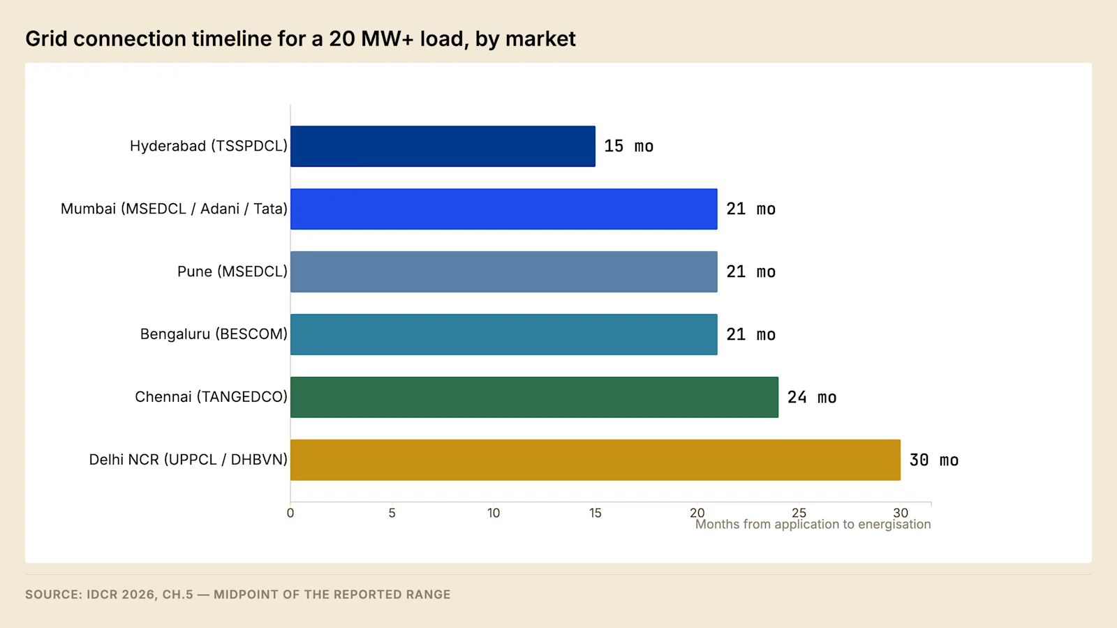
Telangana and Gujarat have established priority handling for data centre connections, and their timelines reflect it. Markets without such arrangements carry the queue that results. The spread between the fastest and slowest major markets exceeds the value of the incentive packages offered by either, which makes connection timeline a more consequential state-selection variable than incentive value.
The upstream position constrains all of these timelines. Powergrid's capital programme and the Green Energy Corridor extensions are adding substantial transmission capacity, and a large proportion of ongoing inter-state transmission projects are running behind schedule according to IEEFA's February 2026 review. Delay in the transmission programme compounds the connection queue rather than relieving it, because it defers the augmentation on which individual connection applications depend.
3.1 Sources of the variation between utilities #
The spread above is produced by administrative differences that can be established before a site decision, rather than by any difference in network condition. Three account for most of it: whether a cell or officer has been designated to carry large-load connections, which removes the handoffs occupying much of stages 2 to 5; whether bay availability is held in a current register rather than established by correspondence; and whether the upstream augmentation is sanctioned rather than identified, which decides whether the application inherits a date or an intention, as set out in Post 2.
The diligence question. Ask the utility to name the last three extra-high-voltage connections above the applicant's size that it has energised, with the application and energisation dates for each. A timeline published in a state policy document states an intention, and three dated pairs describe a demonstrated capability.
3.2 The upstream augmentation programme #
Programme element | Position at the edition cutoff | Source |
Powergrid capital programme | ₹3 lakh crore committed through FY2032 | Mercom India, via IDCR 2026 |
Powergrid outlay, current year | ₹32,000 crore in FY26 | Mercom India, via IDCR 2026 |
Green Energy Corridor Phase 2 | 10,750 ckm and 27,500 MVA, commissioning from March 2026 | Ministry of Power, via IDCR 2026 |
Inter-state transfer capacity | 112 GW installed against 150 GW assessed as required | National Electricity Plan and CEA, via IDCR 2026 |
Inter-state project delivery | Many of 50 ongoing projects running 6–24 months behind | IEEFA, February 2026 |
The last row transfers into a project programme. A sanctioned scheme carries a commissioning date, and an application dependent on it inherits the date rather than the sanction. The corridor position also determines what a strengthening condition is worth contesting: where the augmentation already sits in the sanctioned programme, the applicant is being asked to advance a cost the tariff would otherwise recover.
4. Cost allocation #
The connection charge comprises several components, and the allocation of one of them is negotiable in a way that materially affects project cost.
Component | Normally borne by | Negotiable |
Dedicated line from the network to the site | Consumer | No |
Bay works at the feeding substation | Consumer | No |
On-site receiving substation | Consumer | No |
Metering and protection at the interface | Consumer | No |
Upstream network strengthening | Contested | Yes |
General network reinforcement | Utility, recovered through tariff | Yes |
The contested line is upstream strengthening. Where a connection application triggers a requirement to reinforce the network above the point of connection, the utility will ordinarily attribute the cost of that reinforcement to the incoming load. Whether that attribution is correct depends on whether the reinforcement serves only the new load or also relieves a pre-existing constraint and serves future consumers.
The developer's position is established by independent network analysis conducted in parallel with the utility's system study rather than in response to it. Where the analysis demonstrates that reinforcement delivers benefit beyond the applicant's load, a proportionate allocation is generally achievable. Accepting full attribution without analysis is common and expensive, and the opportunity to contest it closes once the connection agreement is executed.
4.1 The basis of attribution #
The contest turns on a principle Indian regulation states in general terms and applies case by case: cost caused by a consumer is recovered from that consumer, and cost conferring a general system benefit is recovered through the tariff. Connection charging sits between the two, at a position set by the state supply code and the terms the State Commission has approved rather than by any national rule.
Charging basis | What the applicant funds | Where the balance falls |
Shallow | Assets dedicated exclusively to the connection | Utility recovers reinforcement through the tariff |
Deep | Dedicated assets plus all reinforcement triggered by the connection | Applicant carries the whole attributed cost |
Shared, on a benefit test | Dedicated assets plus a proportion of reinforcement | Proportion set by the benefit conferred beyond the applicant |
Large-load practice sits close to the second row by default and moves toward the third only where the applicant advances an argument, because full attribution is defensible wherever it goes uncontested. The counter-analysis answers the utility's questions on the utility's network model, and produces a result its own planners can reproduce.
Test | What it establishes |
Loading of the feeding element before the new load | Whether it was already approaching its limit |
Loading with and without the declared demand | The share attributable to the applicant |
Firm capacity after reinforcement, less the applicant's demand | Whether headroom is created beyond the requirement |
The utility's register of applications at the node | Whether other consumers will take up that headroom |
The transmission plan and its sanction date | Whether the scheme was already committed |
The third and fourth tests carry the argument, and the timing constraint is absolute. The analysis is commissioned when the application is filed, so that it runs alongside the utility's study. An analysis produced in response to a technical feasibility report is an objection to a document already issued, and it is answered as such.
4.2 Right of way for the dedicated line #
The dedicated line carries the widest range of outcomes in the programme, and the range is produced by land law rather than by engineering.
A licensee placing an electric line does not acquire the land beneath it. The appropriate government may confer on a licensee the powers of the telegraph authority under Section 164 of the Electricity Act, 2003, which permit a line to be placed and maintained across land in which the licensee holds no title. The owner retains title and, under an overhead line, continues to use the surface. Compensation is accordingly assessed for the diminution in land value and for damage caused during construction rather than as a purchase price, and a dispute over the amount is determined by the district administration. An overhead line additionally requires prior approval of the appropriate government under Section 68 of the same Act, on its own timetable.
Those powers are confined to a licensee. A consumer constructing a dedicated line for its own supply holds no statutory right of way, which leaves two routes. The works can be executed by the utility as a deposit work, with the utility exercising its powers and the developer funding the cost. Or the developer negotiates a right of user with each landowner, which gives every landowner a position on the critical path of a facility whose completion date is public.
Corridor options for a dedicated extra-high-voltage line — cost per kilometre from IDCR 2026, Chapter 5
Attribute | Overhead line on towers | Underground cable |
Capital cost | Lower | ₹15–25 crore per km in urban conditions |
Principal consent | Right of user across each holding, plus line approval | Permission to open and reinstate from the road authority |
Programme risk | Acquisition, and possible litigation | Utility diversions and reinstatement conditions |
Restoration after a fault | Hours | Days, with jointing |
Constraint at length | None material over these distances | Charging current rising with route length |
The last row is a physical constraint rather than a commercial one. A cable has substantially higher capacitance per kilometre than an overhead line of the same rating, so it generates reactive power in proportion to its length and to the square of the operating voltage. Beyond a certain length the charging current consumes a material part of the conductor's thermal rating and shunt compensation is required. The effect is manageable over the corridor lengths typical of an Indian campus connection, and it becomes a design driver on longer routes at higher voltage.
Field note. Right-of-way exposure is set by the route rather than by the distance. A corridor crossing many small agricultural holdings carries more counterparties and more scope for objection than a longer one following a road reserve. Route selection therefore runs against the cadastral record, and it runs before the point of connection is accepted.
4.3 Deposit works and the agreement that governs them #
A deposit work is an arrangement under which the utility executes works on its own network, or works that will become its assets, and the applicant funds them in advance. The utility designs, procures, constructs, owns and maintains. The applicant pays and inherits nothing except a supply. The arrangement exists because the statutory powers to place a line attach to the licensee rather than to the consumer, as §4.2 sets out, and because work on or adjacent to energised network assets is executed by the licensee under its own safety rules.
The agreement that governs a deposit work is a construction contract in which the funding party holds none of the usual construction-contract rights, so its terms deserve more attention than their length suggests.
Clause | What it fixes | Position to take |
Scope of works | Which assets the utility will build | An itemised scope, not a lump description |
Basis of the estimate | Rates, quantities and provisional sums | The rate schedule, and identification of every provisional item |
Deposit and its timing | When money is paid against the programme | Payment staged against milestones rather than in advance of all works |
Supervision or departmental charge | The utility's overhead on the works | Stated as a rate, with the base it is applied to |
Programme and milestone dates | When each element is to be complete | Dates rather than durations, and a reporting obligation |
Ownership on completion | Whose asset the works become | Recorded expressly, since it affects insurance and access |
Reconciliation on actual cost | How the estimate is trued up | Reconciliation on measured cost, with access to the records |
Refund of unspent deposit | What happens to a favourable outturn | A stated period for refund, and interest where the code allows |
Inspection rights | What the applicant may see and when | Attendance at testing, and copies of test certificates |
Defect liability | Who repairs a failure after energisation | The utility's standard, recorded rather than assumed |
Escalation | Treatment of price movement during execution | The index and the base date, where escalation is permitted |
Termination | Consequences if the connection does not proceed | Recovery of unspent funds, and the treatment of plant already ordered |
Later connections to the same asset | Whether a subsequent user contributes | Whether the state code provides a proportionate refund |
The asymmetry in the arrangement is worth stating plainly. The applicant funds an asset it will not own, has no control over the procurement, cannot substitute a contractor that is performing badly, and holds no remedy for delay unless a remedy has been written into the agreement. That asymmetry is the reason the reciprocal milestones described in §2.4 are worth more than any other negotiated term. It is also the reason the allocation of delay is treated as a separate subject below.
The estimate is the second point of exposure. A utility estimate at this scale is prepared from schedule rates against approximate quantities, and it carries provisional sums for items that cannot be quantified until the route survey and the soil investigation are complete. The gap between estimate and outturn on a corridor of this length is material, and the direction of the gap is not predictable. A reconciliation clause converts the estimate into a payment on account, which is the correct characterisation, and access to the measurement records is what makes the reconciliation checkable rather than declaratory.
The last row of the table repays a direct question to the utility. Where a subsequent consumer connects to an asset the first applicant funded, some state supply codes provide for a proportionate refund to the original contributor, and some do not. On a shared corridor into an industrial or data centre cluster the sums involved can be a large fraction of the original deposit, and the entitlement is worth establishing before the deposit is paid rather than after a neighbour connects.
Route | Who executes | What the applicant controls | Principal exposure |
Deposit work | Utility | Funding and scope agreement only | Programme, cost outturn and quality, with no direct remedy |
Self-execution under utility approval | Applicant's contractor | Contractor selection, programme and sequencing | Conformity to the utility's specification, and rejection at handover |
Self-execution is permitted by some state codes for defined elements, usually the dedicated line and the applicant's side of the interface, executed to the utility's approved design and under its supervision, with the completed asset handed over. The trade is control of the programme against the risk of rejection at handover, and the developer's ability to take it depends on whether its contractor holds the licences and the approved-vendor status the utility requires. Where self-execution is available, it removes the utility's outage planning from only part of the scope: the bay works at the feeding substation, described in §6.1, remain the utility's in every case.
The diligence question. Ask whether the estimate is a firm price or subject to reconciliation, what the refund mechanism is where the actual cost falls below the estimate, and what period the refund is paid within. A satisfactory answer names a clause for each. An answer describing the estimate as final identifies a price that will be revised in one direction only.
4.4 Liquidated damages and the allocation of delay #
Liquidated damages are a sum agreed in advance as payable on a defined breach, so that the injured party recovers without proving its loss. They work where the breach is defined against a date and an identifiable act. They work poorly where the obligation is expressed as a state of readiness, because readiness is contestable and the argument about whether it was reached consumes the advantage the clause was meant to confer.
The starting position on a connection is asymmetric, and the asymmetry has a cause rather than a motive. The connection agreement is drafted by the utility on a standard form, the utility's obligations under the state supply code are expressed as duties rather than as contractual promises to a particular applicant, and the code rarely provides a delay remedy running to the consumer. The developer's obligations, by contrast, are specific, dated and enforceable.
Delay event | Where it falls by default | What to negotiate | Evidence needed to claim |
Applicant does not provide site access for the incoming line | Applicant | A defined access date and a cure period | Dated notices, and the site condition on the date |
Applicant's receiving substation incomplete at the charging date | Applicant | Charging permitted in stages against partial completion | Test records for the completed portion |
Applicant does not take supply by the commencement date | Applicant, through demand charges | Commencement tied to a stage within the applicant's control | The agreement's own definition of commencement |
Utility's bay works late | Utility, without remedy unless written in | A reciprocal milestone with a stated consequence | The utility's own programme, and its progress reports |
Utility's dedicated line late under a deposit work | Utility, without remedy unless written in | Milestones and a reporting obligation under §4.3 | Correspondence, minutes and the measurement records |
Busbar outage refused or deferred | Applicant, as a programme condition | Outage windows identified and reserved at agreement stage | The outage plan and the dated request |
Upstream augmentation late | Applicant, as a condition of supply | Nothing contractual; the position is priced, not claimed | The sanctioned scheme and its published dates |
Statutory approval delayed | Applicant | Nothing; the timetable is not the utility's | Submission and approval dates under §2.5 |
Two rows in that table describe events that are foreseeable rather than exceptional, and treating them as force majeure is a category error that costs a claim. Refusal of a busbar outage during a period of system stress is a normal condition of working on an energised network, described in §6.1, and it is allowed for in the programme rather than claimed for afterwards. Slippage in a sanctioned upstream scheme, described in §3.2, is a condition of the network the applicant elected to connect to, and the remedy is site selection rather than litigation.
The developer's exposure is larger than the sum of the damages it pays, because of where the clauses sit in the contractual chain. Damages recoverable from an equipment supplier or an erection contractor are ordinarily capped at a proportion of that contract's value. The loss caused by the delay is the revenue of a facility that cannot open, together with the carrying cost of the capital already drawn. The difference between the two is unallocated and falls on the developer. Post 1 §5 derives what a delay to the occupancy ramp is worth. Post 12 §2.1 sets out how the same delay presents inside a covenant package.
Extension of time is the mechanism that keeps a programme claim alive, and it is procedural. An entitlement to more time ordinarily depends on notifying the event within a stated period, in a stated form, with the effect on the programme identified. A delay not notified in time becomes the claimant's own delay regardless of who caused it. Where both parties are late over the same period, the practical result in most jurisdictions is that neither recovers, which makes concurrency a defence rather than a claim and gives the party with the better records the advantage in any negotiation.
A remedy that exists independently of the contract is worth knowing about, because it is often the only one available. A distribution licensee operates under standards of performance regulations made by the State Commission, which set timeframes for defined services and, in several states, provide compensation where the timeframe is missed. That remedy is regulatory rather than contractual, it is claimed through the licensee and escalated through the forums in §4.5, and its quantum is usually modest against the loss. Its value lies in creating a record of default that supports the larger case.
Field note. Delay claims on connection works are decided on contemporaneous records rather than on the merits as remembered afterwards. The programme, each dated request, each response, the minutes of every progress meeting and the site diary are the evidence, and they are made at the time or not at all. A developer that treats its own records as an internal administrative task, and reconstructs them when the dispute arises, has usually lost the argument before it starts.
4.5 Dispute and appeal routes for a refusal or a disputed charge #
What is being disputed determines where the dispute goes, and choosing the wrong forum costs the time the applicant is trying to save. Three categories separate cleanly, and each has its own chain.
Subject of the dispute | Forum of first instance | What the applicant must produce | What the route will not deliver |
Refusal to connect, or delay in connecting | The licensee's internal grievance mechanism, then the Consumer Grievance Redressal Forum, then the Electricity Ombudsman | The application, the dated correspondence, and the licensee's reasons | A direction that overrides a genuine network constraint |
Quantum or basis of a charge | The State Commission, which approves the charges a licensee may levy | The estimate, the schedule of rates relied on, and the tariff order in force | A refund of amounts accepted without protest |
A technical determination, such as a strengthening condition, a point of connection or a fault level | A petition before the State Commission | The utility's study, the applicant's independent analysis, and the network model assumptions | A finding that the applicant's engineer is preferred, absent a reproducible analysis |
From the State Commission the route runs to the Appellate Tribunal for Electricity, and from the Tribunal to the Supreme Court on a question of law. Both stages are available to a consumer of this size, and both are slow relative to a construction programme. That mismatch is the most important practical fact about the appeal route, and it is the reason the leverage described in §4 exists only before the connection agreement is executed. A developer that is right on the law, and needs power within the year, has an incentive to settle that the utility can calculate as easily as the developer can.
Three procedural points preserve a position that would otherwise be lost by conduct rather than by argument.
The first is payment under protest. Where a disputed charge must be paid for the connection to proceed, paying it while recording the protest in writing at the time of payment preserves the claim to recover it. Payment without protest is ordinarily treated as acceptance of the basis on which it was levied, and the acceptance is difficult to withdraw afterwards. The protest states what is disputed and on what grounds, and it is sent to the officer who raised the demand rather than filed internally.
The second is the interim position. A petition does not ordinarily suspend the obligation to pay or the utility's ability to proceed, so the applicant should decide in advance whether it seeks interim relief and on what terms. A connection held up while a dispute is heard costs more than the charge in almost every case at this scale, which is why the usual course is to proceed under protest and litigate afterwards.
The third is the choice between a case-specific dispute and a general determination. Where the disagreement concerns the basis on which large loads are charged rather than the arithmetic of one estimate, a petition seeking a determination of general application can be brought, often more effectively by an industry body than by a single applicant. It is slower for the applicant that brings it and it changes the position for every applicant that follows, which makes it the appropriate route for a developer with a pipeline in the state rather than a single project.
None of these routes is available on a satisfactory basis unless the applicant's own record is complete: the application as filed, the inputs it supplied to the study, its correspondence with each officer, and the independent analysis commissioned in parallel under §4.1. The timing rule in §4.1 and the record-keeping discipline in the preceding subsection are the same rule seen from two ends, and this subsection is where the value of both is realised or lost.
5. Four supply structures #
The commercial arrangement under which power is taken must be selected before the connection application is filed, because it determines the applicant, the point of connection, and the metering arrangement.
Distribution licensee supply is the default. It is fully regulated, requires no procurement effort, and carries no counterparty risk. It is the most expensive of the four and is generally correct for a first phase below approximately 10 MW while the campus establishes itself.
Open access operates under Section 42 of the Electricity Act, 2003, which gives a consumer the right to procure electricity from a supplier of its choice using the existing network on payment of the applicable charges. The Green Energy Open Access Rules, 2022 reduced the eligibility threshold for green power well below data centre scale. The headline generation tariff is only one component of the delivered cost, and the surcharges and wheeling charges that complete it are examined in Post 7.
Captive and group captive operate under Section 9 of the Electricity Act and the Electricity Rules, 2005. A captive generating plant serving multiple users requires the captive users collectively to hold at least twenty-six percent of the ownership and to consume at least fifty-one percent of the electricity generated on an annual basis, in proportion to their shareholding. The structure exempts the consumer from cross-subsidy surcharge and additional surcharge in most states, which is frequently worth more than the difference in generation tariff. The compliance burden is real and the consumption test is audited.
A distribution licence held by the developer is the newest of the four and the most consequential. A campus operator holding a licence ceases to be a customer of the distribution licensee and becomes a peer utility, able to build its own internal network, procure directly and supply its tenants.
The licence route has moved from proposal to precedent. In April 2026 the Andhra Pradesh cabinet approved a power distribution licence for Google's Visakhapatnam data centre hub, held through an Indian subsidiary and a joint venture with Adani Infra, and the state has since published a framework under which data centres may apply for distribution licences in their own right. Gujarat's Data Centre Policy 2026–29 provides an equivalent route for eligible developers subject to a minimum approved IT load.
Three consequences follow for a developer evaluating the structure. Electricity moves from operating cost to capital cost, which matters because electricity is a large fraction of a hyperscale facility's operating cost. Tariff arbitrage between states compresses, because a licensed operator negotiates with the state regulator rather than the distribution licensee. And the counterparty for the connection changes, which is why the decision belongs before the application rather than after it.
Structure | Typical landed cost | Setup effort | Best suited to |
Distribution licensee supply | Highest | Low | First phase, below 10 MW |
Open access | Moderate | Medium | 10–100 MW in states with moderate surcharges |
Group captive | Lower | High | Above 25 MW in high-surcharge states |
Developer distribution licence | Project-specific | Very high | Large campuses in enabling states |
5.1 Conditions attaching to the licence route #
A distribution licence is granted by the State Commission for a defined area of supply, and it carries obligations a consumer does not have. The licensee supplies every applicant within its area, maintains the network to the Commission's standards of performance, files its tariff for approval, and reports against the Commission's regulations. A campus operator taking this route acquires a regulated business alongside its data centre business.
The Andhra Pradesh campus is planned at a scale of 1 GW across Adavivaram, Tarluvada and Rambilli, with groundbreaking in April 2026 against a commissioning target in 2028. Four questions establish whether the route is available and worth taking elsewhere.
Question | What the answer determines |
The proposed area of supply, and who else is inside it | Whether an obligation toward third parties arises |
The incumbent licensee's position | The opposition the application will meet |
The network the licence requires the applicant to own | Which campus plant becomes licensed plant |
The surrender conditions | What a purchaser of the campus inherits |
5.2 The dedicated facility route #
A fifth arrangement sits between taking supply and holding a licence, and it is in proceeding rather than in policy. A developer may petition the State Commission to construct a dedicated transmission facility serving its own campus at a voltage the distribution licensee does not operate, owning the substation while remaining a consumer. A petition on the MERC hearing register, carried as Petition/Diary No. 175 of 2026, seeks approval for a dedicated gas-insulated substation at Ambernath, filed by a developer whose principal business is real estate.
Where the campus load requires a voltage above the distribution licensee's system, the choice narrows to a dedicated facility or a licence. The dedicated facility avoids the licence obligations described above and delivers none of the procurement freedom, so it answers a constraint of voltage rather than of cost.
6. Long-lead plant #
Lead times for large power transformers and extra-high-voltage switchgear extended across global supply chains after 2022 and have not fully normalised. This produces a sequencing problem with no comfortable resolution.
Ordering before the connection agreement is executed means carrying inventory risk on equipment specified against a utility requirement that is not yet final. Ordering after execution adds the full manufacturing lead time to the critical path, at the point in the programme where the building is otherwise complete. Most experienced Indian developers order at the technical feasibility stage, once the specification is stable enough to commit but before the agreement is signed, and accept the residual risk.
The constraint is upstream of any individual project. India's installed substation transformation capacity must grow substantially by 2030 against a manufacturing lead time that the India Data Centre Review 2026 places at 18 to 24 months, so the constraint applies to the utility's own augmentation programme as much as to the developer's plant.
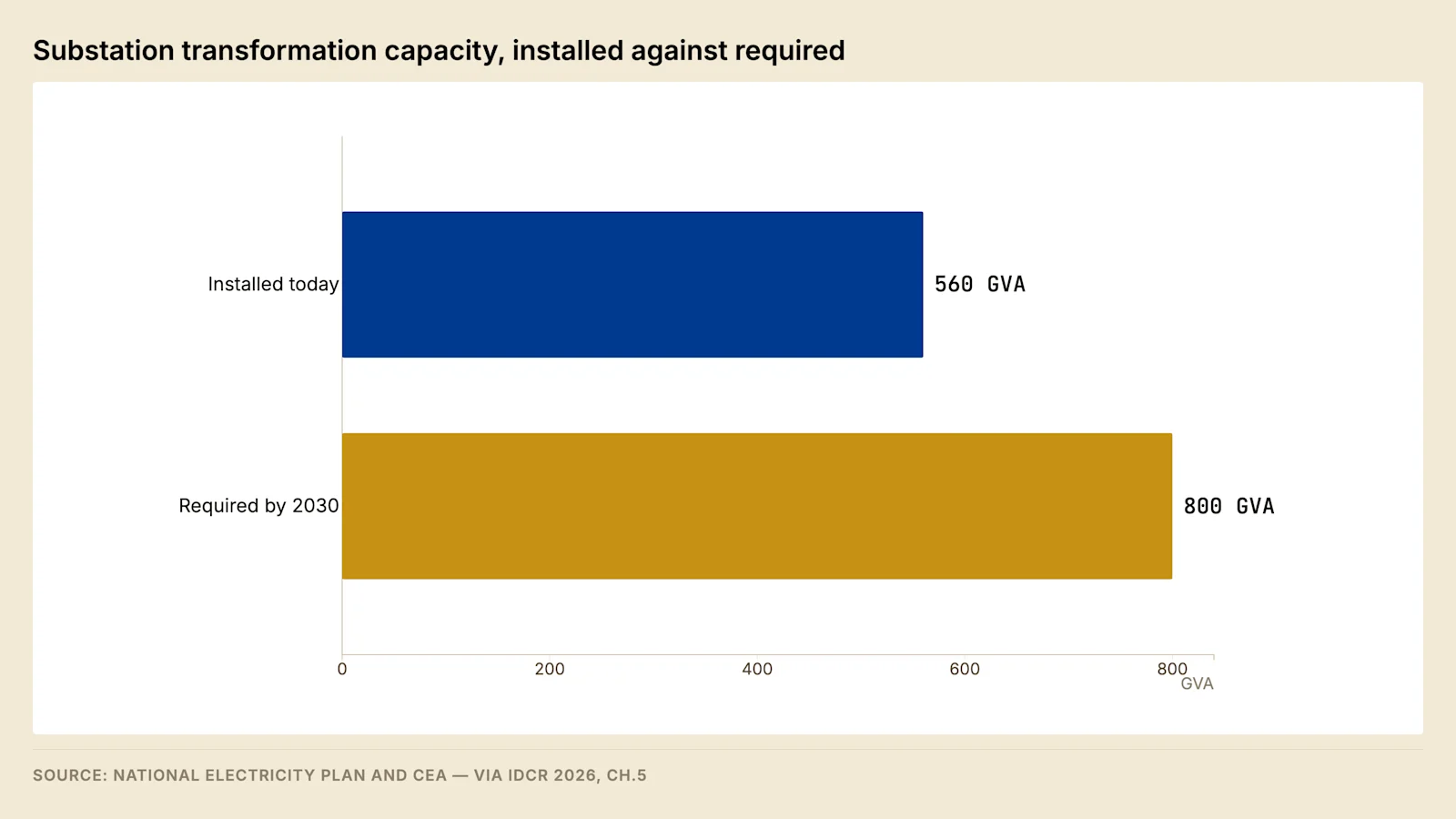
6.1 Bay construction at an energised substation #
Bay works at the feeding substation appear on the programme as a short item and behave as a long one, because most of the work is executed adjacent to live equipment.
A bay is the plant connecting one circuit to the busbar: isolators, breaker, instrument transformers, surge arresters, the structure carrying them, the control and protection cabling, and the relay panel. Erection is measured in weeks, and two constraints unrelated to erection set the duration.
Activity | Live working possible | What sets the duration |
Bay allocation and layout confirmation | Not applicable | A spare bay position in the switchyard |
Civil works, foundations and trenches | Yes, with clearances maintained | Access around energised equipment |
Structure erection and equipment placement | Partly | Crane operation near live conductors |
Busbar connection and jumpering | No | Grant of a busbar outage |
Testing and commissioning onto the bus | No | A second outage, and stability proving |
The first constraint is the outage. Connecting a new bay to an energised busbar requires that busbar to be taken out of service, and an extra-high-voltage outage is granted by the load despatch centre under an outage plan rather than by the substation. Outages concentrate in the low-demand months and are refused during system stress, so a bay missing its window waits for the next.
The second is the availability of a bay position. A switchyard laid out for a fixed number of bays has no spare position once they are occupied, and extending it requires land inside the substation boundary, a busbar extension and a longer outage. Where no extension is possible the connection requires a new substation.
The diligence question. Ask whether the feeding substation holds a spare bay at the required voltage and when the next planned busbar outage falls. A satisfactory answer identifies the bay by its position in the switchyard layout and names an outage window.
6.2 Factory testing and inspection of long-lead plant #
Ordering long-lead plant early, as §6 recommends, transfers a set of decisions from the site to the manufacturer's works, and those decisions are made at the tests. Three categories of test exist and they establish different things, which is why a contract that names only "manufacturer's standard tests" has not specified anything.
Test category | Performed on | What it establishes | What it releases |
Type test | A representative unit of the design | That the design meets its stated performance | The design, once, for a family of units |
Routine test | Every unit produced | That this unit was manufactured correctly | The individual unit for despatch |
Acceptance and special test | The contract units, as agreed | Characteristics specific to this application | Contractual acceptance and the payment milestone |
Witnessing matters because of where a defect is corrected. A winding fault found during an induced overvoltage test at the works is corrected in the works, with the tank open, the plant on the shop floor, and the manufacturer's engineers present. The same fault found after installation is corrected at the site, under an outage, at a distance from the workshop, with the erection contractor demobilising and the programme running. Waiving the witness is therefore a decision to accept the second case in exchange for a few days of travel and attendance.
For a power transformer, the tests worth attending in person are those whose interpretation is contestable rather than those whose result is a pass or a fail. Ratio, vector group, winding resistance and no-load current are documentary. Impedance and load loss carry a commercial consequence, and the tolerance on impedance is a negotiated figure rather than a physical constant. A transformer whose impedance differs from the specified value changes the fault level calculated in §2.7. The same deviation moves the voltage regulation described at §2.9 and the compensation sized against it. Impulse and induced overvoltage tests with partial discharge measurement are the tests that establish insulation integrity, and partial discharge in particular is read from a trace rather than from a number, so a witness who has seen the trace is in a different position from one who receives the certificate. The tap changer operation test proves the mechanism through its full range under load conditions the site will not reproduce for years.
For extra-high-voltage switchgear, mechanical operation counts, closing and opening timing, contact resistance, dielectric tests and interlock function are the routine set, together with gas tightness and moisture content on gas-insulated equipment. Timing is the test that connects to the protection philosophy at §2.10, because the breaker's opening time is one of the terms in every grading calculation, and a breaker slower than assumed invalidates the margins the settings were built on.
Two consequences of factory testing reach beyond the works. The certificates generated there are the same certificates the Electrical Inspectorate requires in the dossier at §2.5, which also records why they are difficult to obtain once the order has closed. The witnessed test report is also, on most supply contracts, the event that releases despatch and triggers a payment. A unit despatched against an unwitnessed test has been accepted in substance, and the developer's position on any defect found later is correspondingly weaker.
The interval between despatch and energisation carries work that is invisible in a quoted lead time and is regularly omitted from programmes. A large transformer travels drained of oil and filled with dry gas, over a route that has been surveyed for bridge capacity, overhead clearance and turning radius, on a vehicle procured for the purpose. On arrival it is placed, assembled, filled through an oil processing plant, circulated and dried, and tested again before it is energised. Each of those steps has a duration and the sequence cannot be compressed by adding resources. A programme that shows the transformer energised in the week of its arrival has omitted this interval entirely.
The diligence question. Ask for the manufacturer's works order number, the reserved slot in the test bay, and the date of the transport route survey. A satisfactory answer produces all three. A lead time quoted without a works order and a reserved slot states an intention on the part of the manufacturer rather than a position in its production programme.
7. Failure modes #
Failure mode | Consequence | Mitigation |
Applying for phase-one load only | System study reopened, queue position lost | Declare full built-out load at first application |
Land committed before the system study returns | Land capital stranded if the site cannot be powered | Apply on an option agreement |
Full strengthening attribution accepted without analysis | Avoidable cost, unrecoverable after execution | Contest with independent network analysis |
Transformer ordered after the connection agreement | Manufacturing lead time added to the critical path | Order at technical feasibility stage |
Overhead line assumed, right of way contested | Extended acquisition and possible litigation | Price underground cable in the base case for urban sites |
Supply structure decided after connection | Reapplication, or a suboptimal structure locked in | Decide before the application is filed |
Electrical inspectorate dossier assembled at completion | Approval delay with a commissioned facility standing idle | Maintain the inspection dossier continuously through construction |
Fire and life safety treated as a closing item | Occupancy blocked on a completed facility | Run National Building Code Part 4 compliance as a parallel workstream |
Non-convergence accepted without its recorded cause | A data defect funded as a strengthening requirement | Require the failure to be classified before the report is issued |
Fault level accepted without a stated horizon year | Switchgear stranded by the next connection at the same node | Obtain the level and its horizon in writing at feasibility stage |
Protection philosophy approved after panel manufacture | Every utility comment becomes a paid variation | Reach approval in principle before the panel enquiry is issued |
Telemetry point list agreed during commissioning | Charging held while points are verified with the despatch centre | Agree and sign the point list at detailed design |
Communication paths redundant but not route diverse | Protection signalling and telemetry lost in one excavation | Specify physical route diversity, and test the changeover |
Deposit work estimate treated as a firm price | No reconciliation, and no refund of a favourable outturn | Contract for reconciliation on measured cost with access to records |
Disputed charge paid without a written protest | The claim to recover it is treated as waived | Record the protest at the time of payment, to the officer demanding it |
On-site generation added after energisation without a study | Protection settings invalid, and approval on the critical path | Declare parallel-operating plant at application, not at installation |
Field note. The instruction that reverses standard practice is to apply for the connection before closing the land, on an option agreement rather than a completed purchase. A system study returning a network strengthening condition is a negotiating position where the land is not yet committed and a sunk cost where it is. The document is identical in both cases and the difference is the date of the land transaction.
8. Worked timeline #
Model assumption — 60 MW IT load campus, 132 kV connection, enabling state, no litigation on right of way
Month | Grid workstream | Construction workstream |
0 | Load estimation, voltage determination, pre-application meeting | Site option secured |
1–2 | Connection application filed with the STU | Geotechnical investigation, survey |
2–6 | System study, load flow and short circuit analysis | Land closure, plan approvals |
6–8 | Technical feasibility report, cost estimate, attribution negotiated | Site mobilisation |
6–9 | Long-lead plant ordered — transformers, EHV switchgear | Structure |
8–9 | Connection agreement executed, deposit paid | Foundations |
9–20 | Right-of-way acquisition and line construction | Shell complete by month 16 |
10–22 | Bay construction at the feeding substation | MEP first fix |
14–26 | On-site receiving substation, transformer delivery and installation | MEP second fix |
26–29 | Pre-commissioning, protection coordination, electrical inspectorate | Integrated systems testing |
29–31 | Charging, staged energisation, load bank proving | Handover |
31 | Commercial operation |
The building reaches completion roughly halfway through the programme, and the facility earns nothing for the remainder. That interval, rather than the connection charge, is the real cost of the connection programme, and it is the quantity a financial model should carry. Post 1 sets out how a delay at this stage propagates through the occupancy ramp.
Forward look #
Three developments would change the programme materially.
The first is whether additional states adopt the distribution licence route now that Andhra Pradesh has granted one and published a framework. Each state that does so removes a gatekeeper from the process for campuses large enough to qualify.
The second is whether the transmission augmentation programme recovers its schedule. Connection timelines are bounded below by the availability of upstream capacity, and sustained slippage in inter-state projects transfers directly into the connection queue.
The third is the transformer and switchgear supply position. Manufacturing capacity is being added in India, and a material reduction in lead time would remove the sequencing problem described in section 6 and shorten the critical path for every project simultaneously.
FAQ #
How long does a data centre grid connection take in India? At extra-high voltage the process runs from application to commercial operation over a period measured in years rather than months, and the duration varies substantially by utility. Section 3 sets out the variation between metropolitan markets.
What is the critical path in an Indian data centre development? The grid connection, for any facility above roughly 60 MW of IT load. Right-of-way acquisition for the incoming line and the procurement of long-lead electrical plant are the two activities within it that determine the outcome.
Should the connection application be filed before the land is acquired? Yes, on an option agreement. A system study returning a strengthening condition is a negotiating position where the land is not committed and a sunk cost where it is.
Who pays for upstream network strengthening? The utility will ordinarily attribute it to the incoming load. Where independent analysis demonstrates that the reinforcement also relieves a pre-existing constraint or serves future consumers, a proportionate allocation is generally achievable, but only before the connection agreement is executed.
What is a developer distribution licence and who has one? It permits a campus operator to procure and distribute electricity directly rather than taking supply from the distribution licensee. Andhra Pradesh approved one for Google's Visakhapatnam hub in April 2026 and has published a framework for further applications; Gujarat provides an equivalent route under its data centre policy.
What can be done when a connection is refused or a connection charge is disputed? The forum depends on the subject. A refusal or a delay is a service failure, taken through the licensee's grievance mechanism, the Consumer Grievance Redressal Forum and the Electricity Ombudsman. A charge or a technical determination goes to the State Commission, with an appeal to the Appellate Tribunal for Electricity. Section 4.5 sets out what each route requires and why a disputed charge is paid under written protest.
Sources #
Electricity Act, 2003, Sections 9, 42, 68 and 164
Electricity Rules, 2005, captive generating plant conditions
Ministry of Power, Green Energy Open Access Rules, 2022
CEA, Technical Standards for Connectivity to the Grid Regulations
CEA regulations on measures relating to safety and electric supply — named at instrument level, for the statutory basis of Electrical Inspectorate approval
CEA regulations on the installation and operation of meters — named at instrument level, for the metering interface
State Commission standards of performance regulations — named at instrument level, for the regulatory remedy in section 4.4
Appellate Tribunal for Electricity, Consumer Grievance Redressal Forum and Electricity Ombudsman, constituted under the Electricity Act, 2003 — named as forums, for the appeal routes in section 4.5
Ministry of Power, Green Energy Corridor Phase 2, via IDCR 2026
Mercom India, Powergrid capital programme, via IDCR 2026
National Electricity Plan and CEA transmission assessments, via IDCR 2026
Government of Gujarat, Data Centre Policy 2026–29, June 2026 (via NASSCOM Public Policy)
National Building Code of India, Part 4
India Data Centre Review 2026 (v2.3, edition cutoff 28 July 2026), Chapters 5 and 10 — India Energy Atlas
MERC hearing register, Petition/Diary No. 175 of 2026
Google Press Corner, India AI Hub groundbreaking, 28 April 2026
IEEFA, inter-state transmission progress review, February 2026, via IDCR 2026
The worked timeline and the cost allocation table are modelled by India Energy Atlas and are labelled as model assumptions. IDCR 2026 figures are quoted at the locked edition snapshot of 13 July 2026; live Atlas products may carry newer records.
This post was revised against the measured GenAI load-profile analysis — see the working note for the load derivation, ramp rates and the peak-to-nameplate ceiling.
Read the full series — The Indian Data Centre Playbook, twelve parts from unit economics to exit.
Next in the series — Part 4: Designing the Electrical Topology. The cost of redundancy, the fault domain, and how the topology decision affects the tenant pool.
India Energy Atlas tracks interconnection queues, transmission plans, and open access charges across Indian states. See energymap.in/pricing.
Sources & method
- Electricity Act, 2003, Sections 9, 42, 68 and 164 - Electricity Rules, 2005, captive generating plant conditions - Ministry of Power, Green Energy Open Access Rules, 2022 - CEA, Technical Standards for Connectivity to the Grid Regulations - CEA regulations on measures relating to safety and electric supply — named at instrument level, for the statutory basis of Electrical Inspectorate approval - CEA regulations on the installation and operation of meters — named at instrument level, for the metering interface - State Commission standards of performance regulations — named at instrument level, for the regulatory remedy in section 4.4 - Appellate Tribunal for Electricity, Consumer Grievance Redressal Forum and Electricity Ombudsman, constituted under the Electricity Act, 2003 — named as forums, for the appeal routes in section 4.5 - Ministry of Power, Green Energy Corridor Phase 2, via IDCR 2026 - Mercom India, Powergrid capital programme, via IDCR 2026 - National Electricity Plan and CEA transmission assessments, via IDCR 2026 - Government of Gujarat, Data Centre Policy 2026–29, June 2026 (via NASSCOM Public Policy) - National Building Code of India, Part 4 - India Data Centre Review 2026 (v2.3, edition cutoff 28 July 2026), Chapters 5 and 10 — India Energy Atlas - MERC hearing register, Petition/Diary No. 175 of 2026 - Google Press Corner, India AI Hub groundbreaking, 28 April 2026 - IEEFA, inter-state transmission progress review, February 2026, via IDCR 2026 The worked timeline and the cost allocation table are modelled by India Energy Atlas and are labelled as model assumptions. IDCR 2026 figures are quoted at the locked edition snapshot of 13 July 2026; live Atlas products may carry newer records. Photography: - Photo by Jonathan Hanna on Unsplash (https://unsplash.com/photos/low-angle-photo-of-transmission-post-08ai5EDtn9k?utm_source=india_energy_atlas&utm_medium=referral) - Photo by Evgeniy Alyoshin on Unsplash (https://unsplash.com/photos/a-couple-of-power-lines-sitting-next-to-each-other-FXw3zkbqd0w?utm_source=india_energy_atlas&utm_medium=referral)