
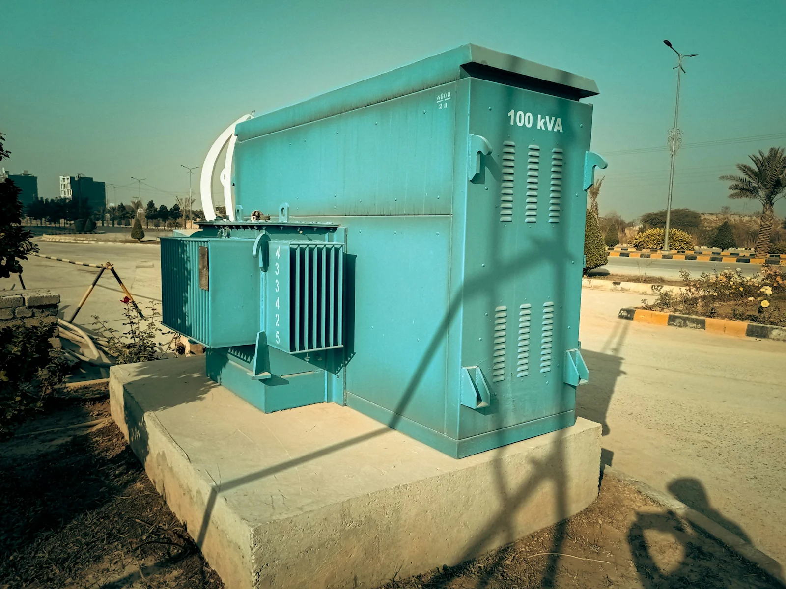
Site Selection for Indian Data Centres: Screening Grid, Water and Fibre Before Land
A screening sequence for Indian data centre sites ordered by irreversibility, covering EHV substation headroom, transmission corridor capacity, water availability under drought, fibre diversity and the load characteristics that determine tariff exposure.
The short answer. Indian data centre sites should be screened in order of irreversibility: extra-high-voltage substation headroom, upstream transmission corridor capacity, fibre and cable-landing access, water availability under drought conditions, land, then policy incentives. A large campus is a transmission planning problem rather than a distribution connection, and land price is the last variable that materially affects the outcome.
This post sets out a screening sequence for Indian data centre sites, the technical basis for each screen, and the evidence a site file needs to carry before capital is committed. It is written for the developer assembling a shortlist, the investment committee testing one, and the distribution or transmission planner who receives the resulting connection application.
The organising principle is irreversibility. A screen that can be failed and recovered from cheaply belongs late in the sequence; a screen that permanently constrains the project belongs early. Commercial terms on land can be renegotiated, and a mediocre land acquisition can be written down and absorbed. A transmission corridor with no sanctioned augmentation cannot be improved by any action available to the developer, and a site dependent on one is not a site.
1. The screening sequence #
Rank | Screen | Disqualifying condition | Time to verify |
1 | EHV substation headroom | No firm N-1 capacity for the full built-out load within the required timeline | 2–4 weeks |
2 | Upstream corridor capacity | Feeding line loaded above 80% at peak with no sanctioned augmentation | 3–6 weeks |
3 | Fibre and latency | Fewer than three physically diverse routes, or dependence on a single provider | 1–2 weeks |
4 | Water under drought | No assured non-potable source at design WUE in a 1-in-20 dry year | 3–8 weeks |
5 | Land | Title, zoning, contiguity, flood return period, ground conditions | 6–16 weeks |
6 | Policy and incentives | Eligibility threshold unmet, or incentive value below the cost of relocating to claim it | 2–4 weeks |
7 | Talent and access | No continuous-shift skilled operations pool within commuting distance | 1–2 weeks |
Most site selection processes run this sequence in reverse, beginning with an available land parcel and a state incentive package and working toward the grid. The consequence is that the connection study, which is the screen capable of terminating the project, arrives after the land is committed and the negotiating position has been surrendered. Sequencing the screens by irreversibility means the cheapest and most decisive tests are performed while every option remains open.
1.1 The anchor specification #
The seven screens are ordered by irreversibility, and their relative weight is set by the workload the campus is intended to carry. That specification is established before the sequence runs, because it determines which screen binds.
Anchor attribute | What it fixes | Screen re-weighted |
Workload class mix | Deferrable share of load | Corridor capacity |
Market served | Hour of peak demand | Tariff exposure |
Contracted rack density | Apparent power per acre | Land, water, headroom |
Resilience class | Electrical topology | EHV headroom |
Term and expansion rights | Load declared at application | EHV headroom |
Workload classes are defined in Post 10 and resilience classes in Post 4.
The diligence question is which workload classes will occupy the first block and which market they serve. A satisfactory answer names the class mix and the served market rather than a peak load figure, because the peak is an output of those two rather than an independent input.
1.2 The evidence that closes each screen #
A screen is closed by a document rather than by an opinion.
Screen | Artefact, and its issuer | What it must state |
EHV headroom | Capacity response from the STU or licensee | Firm capacity, committed load deducted, validity date |
Corridor capacity | Load flow extract, or the transmission plan entry | Post-contingency loading and augmentation status |
Fibre and latency | Route maps and duct records from each provider | Chainage, duct ownership, shared structures |
Water under drought | Municipal allocation letter, with the CGWB record | Volume, its priority in a deficit year, unit categorisation |
Land | Title chain, encumbrance record, zoning and flood record | Marketable title, permitted use, flood return period |
Policy | The notified instrument and the order under it | Eligibility, sanctioning authority, disbursement route |
An artefact closes a screen to the extent that three attributes appear on its face: the identity of the issuer and the authority under which the statement was made, the date on which the statement was true, and the period for which it remains valid. A capacity statement without a validity date is a historical record of a network condition. A title opinion without its search period is an opinion about an unstated interval. A policy extract without the instrument number under which it was notified cannot be traced to the order that would carry it into effect.
The failure mode is the comfort given verbally at a pre-application meeting. Utility officers indicate feasibility in good faith on the information available to them, and the indication does not bind the system study that follows.
The land and policy screens generate the largest number of artefacts and the longest verification intervals in the table above, and the inventory they produce is set out in section 9.
2. Deriving the connection requirement #
The connection requirement is derived from IT load outward, and each step introduces a multiplier that is frequently omitted from early-stage estimates.
Model assumption — connection derivation, 100 MW IT load facility
Step | Calculation | Result |
IT load | Design basis | 100 MW |
Total facility power | IT load × design PUE 1.40 | 140 MW |
House and ancillary load | Offices, lighting, security, site services | +3 MW |
Apparent power | 143 MW ÷ 0.90 power factor | 159 MVA |
Firm connection under N-1 | Full load available with one transformer out of service | 159 MVA firm |
The final row is the one most often omitted, and it is the one that determines whether a site works. Firm capacity is the capacity available with the largest single element out of service, which for a two-transformer substation is the rating of one transformer rather than the sum of both. Installed capacity and firm capacity are different quantities, and a substation nameplate describes the first.
Substation condition | Capacity |
Installed, two transformers | 320 MVA |
Firm under N-1, one transformer out | 160 MVA |
Less existing committed load | (60 MVA) |
Available firm headroom | 100 MVA |
A facility requiring 159 MVA firm does not fit that substation, notwithstanding an installed nameplate of double what it needs. Screening against installed capacity rather than firm headroom is the most common technical error in Indian site selection, and it is not detectable from a map.
Voltage level by connected load — indicative
Connected load | Typical connection voltage |
Up to 1 MW | 11 kV |
1–5 MW | 11 or 33 kV |
5–25 MW | 33 kV |
25–75 MW | 66, 110 or 132 kV |
75–200 MW | 220 kV |
Above 200 MW | 400 kV, or dedicated 220 kV bays with multiple sources |
These bands are indicative. The governing standard is the CEA Technical Standards for Connectivity to the Grid Regulations, read with the applicable state grid code, and several states impose stricter thresholds than the national standard.
The consequence of the derivation is a change in the character of the project. A campus at 33 kV is a commercial process with a distribution licensee, conducted under a published tariff schedule and measured in months. A campus at 220 kV is a planning process with the State Transmission Utility, requiring a system study, bay construction at an existing substation or a new dedicated substation, and a right of way for the incoming line. It is measured in years, and it is examined in Post 3.
Field note. Distributing a load of this size at 33 kV drives the incoming feeder count to a number no distribution licensee will willingly operate, and it is the resulting switching arrangement rather than the current itself that sets the threshold. A campus above the IT load stated below should be planned as EHV-connected from the outset, with an on-site step-down substation inside the boundary. Establishing this after a land parcel has been committed is the most expensive correction available in Indian data centre development.
Quantity at 33 kV distribution | Value |
Feeder current at the load in question | Order of 2,780 A |
Practical capacity per feeder | 20–35 MVA |
Incoming feeders implied | Six to ten |
IT load above which EHV is planned from the outset | Approximately 60 MW |
On-site step-down arrangement | 220/33 kV or 132/33 kV |
Model assumption — feeder count derived from the load and the per-feeder capacity band.
2.1 The standard governing the derivation #
The arithmetic of the derivation is fixed. The voltage at which the resulting load is served is a regulatory determination, made by the licensee or the State Transmission Utility under the CEA Technical Standards for Connectivity to the Grid Regulations, read with the applicable state grid code and, where the point of connection sits on the inter-state system, with the national grid code.
The physical reason for the ladder is the relationship between voltage and current. For a given quantity of power, current falls as supply voltage rises, and conductor losses fall with the square of that current. The second constraint is fault level: as connected load grows at a fixed voltage, the prospective fault current at the busbar approaches the interrupting rating of economically available switchgear, and the network is taken up a voltage level to keep the duty inside the rating.
The diligence question is to ask the licensee, in writing, for the voltage of supply applicable to the declared demand under its supply code. A satisfactory answer cites the provision and states the demand band, rather than describing what has been done for other consumers. The bands cease to govern where the developer holds a distribution licence, because the applicant is then a licensee rather than a consumer.
2.2 Power factor and the reactive component #
The divisor in the fourth row of the derivation converts real power into apparent power. Network plant is rated in apparent power because conductors, transformers and switchgear heat with the total current they carry irrespective of the phase relationship between current and voltage, and the reactive component contributes to that current while performing no work.
Uninterruptible power supply rectifiers and variable speed drives present a displacement factor close to unity and draw current that is not sinusoidal, so the distortion component depresses the true power factor even where displacement is high. Capacitor banks correct displacement and do not correct distortion, and harmonic mitigation is a design item treated in Post 4. Indian HT and EHV tariff schedules attach an incentive or a penalty to the factor recorded at the interface, so the assumption is both a sizing input and a recurring billing exposure.
The diligence question is which power factor the tariff schedule applies, on what measurement basis, and over what averaging interval.
2.3 Firm capacity and the substation arrangement #
Firm capacity is the capacity deliverable with the single most onerous element out of service, and which element that is depends on the arrangement of the substation rather than on the number of transformers standing in it.
A transformer carries more than one continuous rating, and the higher one depends on forced cooling being in service, so a firm capacity quoted against it is unavailable in the case where the cooling plant has failed.
Two kinds of outage have to be separated before an arrangement can be assessed. A forced outage removes an element without notice when it faults, and the arrangement determines how much of the substation leaves service with it. A planned outage removes an element deliberately so that it can be inspected, maintained or replaced, and the arrangement determines whether that work can proceed with the connection still energised. Planned outages are the more frequent of the two by a wide margin, so an arrangement that survives a fault gracefully while requiring an interruption for routine breaker maintenance will interrupt the campus on a predictable cycle.
Busbar arrangement | Governing contingency | Consequence for a continuous load |
Single bus | Loss of the bus | Every circuit removed; no firm capacity |
Sectionalised bus with coupler | Loss of one section | Surviving section only, limited by the coupler |
Double bus, single breaker | Loss of one bus | Circuits transferred; the transformer governs |
Breaker-and-a-half | Loss of one breaker | No circuit removed; transformer or line governs |
Ring bus | Loss of one breaker | The ring opens; the remaining path carries all flow |
The same five arrangements behave differently again when the element withdrawn is a breaker rather than a bus, and that behaviour is what a campus experiences as availability rather than as a planning statistic.
Busbar arrangement | Effect of a fault on the bus | Effect of maintenance on one breaker | Relative switchyard area |
Single bus | Every circuit lost | Its circuit out of service | Smallest |
Sectionalised bus with coupler | One section lost | Its circuit out of service | Small |
Double bus, single breaker | Circuits transferred to the healthy bus | Its circuit out unless a bypass path exists | Moderate |
Breaker-and-a-half | No circuit lost | No circuit lost | Largest |
Ring bus | No circuit lost; the ring opens | Ring opens; a further outage isolates a circuit | Moderate |
A single bus is the cheapest arrangement and the one that concentrates the most risk, because every circuit terminates on one conductor and a fault anywhere along it removes them all. Sectionalising that bus with a coupler breaker halves the exposure, and the coupler's own rating then limits how much load one section can accept from the other. Where the utility operates the coupler normally open, which is a common measure for holding the fault level at a growing node inside the rating of the installed switchgear, the two sections are separate substations in electrical terms and the firm capacity available to a connection is the capacity of its own section alone. A capacity statement quoted for the substation as a whole overstates what is available to a connection landing on one section of it.
The double bus arrangement gives every circuit a selection between two buses through disconnectors, so a bus can be released for work by transferring its circuits to the other. The circuit breaker remains a single element in each circuit, so maintaining a breaker still removes its circuit unless the design provides a bypass around it, which is what a main and transfer bus arrangement adds.
Breaker-and-a-half removes both limitations by placing three breakers across two buses for each pair of circuits, so no single breaker outage removes a circuit and no single bus outage removes any. The price is the highest breaker count and the largest switchyard area of the five arrangements, together with a protection scheme that has to sum the current measured in two breakers to obtain the current in one circuit.
A ring bus reaches a similar result at a lower breaker count by closing the circuits into a loop, and it is economical while the circuit count stays low. Its weakness appears on the second event rather than the first. Once the ring has opened for a breaker outage it is an open chain, and a fault at the wrong point along that chain isolates a circuit completely. A campus fed from a ring bus therefore has a direct interest in the utility's operating practice during planned work on the ring.
The consequence for the project is that the feeding utility's maintenance programme becomes an input to the campus electrical design wherever the arrangement cannot be maintained without an interruption, because the on-site topology has to carry the load through that interruption. Concurrent maintainability is defined in Post 4, which also sets out the topologies capable of delivering it.
The diligence question is to ask for the single-line diagram of the feeding substation and the contingency list the utility applies to it. A satisfactory answer names the arrangement, states whether the transformer rating quoted is the natural or the forced-cooled rating, and identifies the incoming circuits. Two further questions follow from the arrangement itself: whether any bus coupler or section breaker is operated normally open, and what the utility's planned outage programme requires at that substation over the period covering construction and early operation.
2.4 Committed load and the connection queue #
The deduction line in the headroom table moves faster than any other quantity in the screen. Two things consume firm headroom: load already sanctioned to other consumers but not yet drawn, and applications lodged ahead of the project that have not yet been sanctioned.
Sanctioned but undrawn load is held rather than available, because a consumer paying a demand charge against sanctioned demand retains that capacity whether or not it draws it.
Date | Reported connection queue at one United States utility's substations |
July 2024 | 8 GW |
December 2024 | 26 GW |
Source: Loudoun County data centre brief, via IDCR 2026, Chapter 5.
The diligence question has three parts: the date of the figure, the sanctioned but undrawn load already deducted from it, and the applications ahead of the project at the same node. The failure mode is a decision taken on a capacity statement obtained months earlier, and it surfaces at the technical feasibility stage described in Post 3.
2.5 The land the connection occupies #
The receiving substation sits inside the site boundary, and its area, its access and its platform level are land constraints created by the electrical requirement rather than by the building.
Switchyard area at extra-high voltage differs substantially between air-insulated and gas-insulated equipment at the same voltage, and on a constrained parcel the area available decides the selection before cost does. The transport route for a large power transformer has to be surveyed as an abnormal indivisible load, for bridge capacity, headroom at crossings, turning radii and clearance beneath overhead lines, because a route failure is discovered after the plant has been manufactured. The substation platform is set above a flood level defined against a stated return period, and a site requiring substantial fill carries both the cost and the programme of placing it. Apparent power required per acre rises with rack density, so a parcel adequate at one density is inadequate at another with no change in its physical characteristics. The diligence question is to obtain the abnormal-load route survey and the flood record before the parcel is committed.
The earth grid serving the receiving substation is a further claim on the same land, and its area is set by the soil at the site and by the fault current the grid has to carry. Both quantities are site characteristics rather than design choices, and they are examined in section 9.5 and section 2.7 respectively.
2.6 Transformer rating, impedance and parallel operation #
The transformers at the point of supply set the firm figure quoted to an applicant, and several of their properties move that figure without changing the megavolt-ampere value printed on the nameplate.
Cooling class and the several ratings on one nameplate. A power transformer carries more than one rated output, and each corresponds to a cooling arrangement: natural oil circulation with natural air cooling gives the base output, forced air raises it, and forced oil circulation raises it again. Every step upward is conditional on rotating plant that can fail, lose its auxiliary supply, or be withdrawn for maintenance. A firm capacity quoted against the highest rating therefore carries the availability of the cooling plant inside it, and the substation's own auxiliary supply arrangement becomes part of the campus availability case.
Cyclic and emergency ratings. The limit on loading a transformer is the hot-spot temperature of the winding insulation rather than the nameplate itself, and insulation ageing is a rate that rises with that temperature. A transformer may therefore be loaded above its continuous rating for a defined period at a defined cost in life, and the loading guide within the IEC 60076 series for oil-immersed power transformers sets out how that exchange is computed. A data centre load is close to flat, so it returns none of the overnight cooling interval that a distribution load provides, and a rating derived from a daily cyclic duty does not transfer to it. The diligence question is which rating the quoted firm capacity rests on, and what duration and ambient temperature are attached to it.
Impedance. The percentage impedance of a transformer is the fraction of rated voltage that circulates rated current in one winding with the other short-circuited, and it governs several quantities the project cares about in opposing directions.
Property | Effect of lower impedance | Effect of higher impedance |
Voltage regulation from no load to full load | Improved | Worsened |
Prospective fault current on the secondary side | Raised | Lowered |
Share of load taken in parallel operation | Raised | Lowered |
Mechanical force on the windings during a through fault | Raised | Lowered |
Reactive power absorbed at full load | Lowered | Raised |
A transformer specified for good regulation raises the fault duty on everything downstream of it, which is the interaction examined in section 2.7. A transformer specified for a low fault contribution worsens the voltage seen by the load and increases the reactive power the connection draws, which returns to the power factor exposure described in section 2.2.
Parallel operation. Two transformers share load correctly only where four conditions hold: the same phase sequence, the same vector group and therefore the same phase displacement between windings, the same voltage ratio at the tap positions in use, and impedances close enough that neither unit reaches its rating substantially before the other. A mismatch in ratio drives a circulating current between the units even at no load, which consumes capacity and heats both without delivering anything to the load. A mismatch in impedance divides the load in inverse proportion to the impedances, so the group reaches its limit when the lower-impedance unit reaches its rating and the higher-impedance unit is still short of its own.
Model assumption — load sharing between two parallel transformers of equal rating and unequal impedance
Step | Calculation | Result |
Rating of each unit | Design basis | 160 MVA |
Impedance of unit A | Nameplate | 10.0% |
Impedance of unit B | Nameplate | 12.0% |
Share of load taken by unit A | 12 ÷ 22 | 54.5% |
Share of load taken by unit B | 10 ÷ 22 | 45.5% |
Group loading at which unit A reaches its rating | 160 ÷ 0.545 | 293.6 MVA |
Installed capacity of the group | 160 × 2 | 320 MVA |
Capacity not usable in parallel | 320 − 293.6 | 26.4 MVA |
The group is installed at a stated capacity and delivers less than that figure in service, and nothing on either nameplate reveals the shortfall. The case arises most often where a utility adds a replacement or an additional transformer to an existing bay years after the first was installed, because a unit specified for a later duty will not necessarily share load with the one standing beside it. The impedance of each unit is therefore a question to ask alongside the ratings.
Unit count under an N-1 requirement. The number of transformers in a group determines how large each has to be, because the group has to deliver the firm requirement with any one of them out of service.
Transformers in the group | Rating of each, against the firm requirement | Installed capacity, against the firm requirement |
Two | 100% | 200% |
Three | 50% | 150% |
Four | 33% | 133% |
Adding units lowers the rating each has to carry and lowers the installed capacity the utility has to fund, at the cost of an additional bay, additional switchgear, a larger switchyard and a higher fault level at the busbar. Standardisation on a single unit rating across a utility's estate carries a spares argument that a project cannot influence. The consequence for a screening exercise is that a substation holding three medium units frequently offers more firm headroom than one holding two large units of the same total installed capacity, and the sum of the nameplates does not disclose it.
Losses. No-load loss is present whenever the transformer is energised and does not vary with the load drawn through it. Load loss varies with the square of that load. A data centre presents a high and flat load factor, so load loss dominates the energy dissipated inside the transformer over a year, and a unit selected on first cost will differ from the unit selected on capitalised losses. Where the developer owns the receiving substation, that evaluation is the developer's to make and the outcome is a recurring energy cost carried for the life of the asset.
Tap changer. An on-load tap changer holds the secondary voltage inside its band as the primary voltage varies with system conditions, and its range is specified against the variation expected at that particular point of connection rather than against a generic figure. It is also the transformer's most active mechanical component and therefore its most frequent maintenance item, so the outage regime for tap changer maintenance belongs in the same conversation as the firm capacity figure.
The diligence question is to ask for the nameplate ratings of each transformer with the cooling class attached to each, the percentage impedance of every unit, whether the units are operated in parallel or on separate bus sections, and whether the quoted firm figure assumes a continuous or an emergency rating. Manufacturing lead time for the plant itself, and its effect on a connection programme, are set out in Post 3.
2.7 Fault level headroom as a screening quantity #
Thermal headroom and fault level headroom are separate quantities measured at the same busbar, and a node can pass the first while failing the second. Prospective fault current at a busbar is set by the impedance between that busbar and every source capable of feeding a fault through it, so the level rises as the network around the node is strengthened and as generation is connected near it. A network improved for reliability becomes, at the same time, a network closer to the interrupting rating of the switchgear standing on it.
A load connection contributes little fault current of its own, and the works constructed to serve it contribute a great deal. An additional transformer, a second incoming circuit, or a reinforcement that lowers the impedance to the source all raise the level at the busbar. On the customer side, rotating plant contributes for the first cycles of a fault and converter-coupled equipment contributes a current limited by its own control, so a campus carrying generators and stored energy is not fault-neutral either.
Change at the node | Effect on prospective fault current |
Additional incoming circuit | Raised |
Transformer of lower impedance | Raised |
Additional transformer in parallel | Raised |
Generation connected close to the node | Raised |
Bus section operated normally open | Lowered on each section |
Series reactor inserted in the circuit | Lowered |
Customer rotating plant capable of paralleling | Raised for the duration of its contribution |
Every remedy available for an excessive fault level costs something the connection also wants. Replacing the switchgear is the direct answer and is charged to the connection that caused the excess. Splitting the bus lowers the level on each section and lowers the firm capacity available on each section with it. A series reactor lowers the level and worsens the voltage regulation while adding a continuous loss. A higher-impedance transformer lowers the level and worsens regulation in the same way. The exchange is why the fault level question is settled early rather than during detailed design.
The screening question is whether the switchgear installed at the feeding substation has margin against the level calculated for a horizon year rather than against the level today, because switchgear procured against the present level can be overtaken by the next connection at the same node. The calculated figure is held by the utility and is not published, so at screening the available proxies are the voltage class and vintage of the installed switchgear, whether the utility has recently reinforced the node, and whether any bus section is already operated normally open, which is itself evidence that the level is being managed.
The boundary of this analysis sits at the point of supply. On the customer side the same quantity governs equipment selection and the withstand ratings specified, which is treated in Post 4. The study that establishes the figure formally, and the conditions the utility attaches to its output, are described in Post 3.
The diligence question is to ask for the design fault level of the feeding substation, the level the utility calculates for its horizon year, and whether any switchgear at that node is already at its rating. An answer that quotes only the present level does not establish whether the connection will attract a replacement condition.
2.8 Margins a screening exercise estimates #
A connection application sets a defined set of network calculations running, and each of them decides one margin. A screening exercise cannot commission those calculations, and it can estimate some of the margins from documents a developer is able to obtain. Knowing which is which is what separates a shortlist that survives the study from one that does not.
Margin | Calculation that decides it | Proxy available at screening | Limitation of the proxy |
Firm capacity at the point of supply | Steady-state load flow | Firm headroom in the capacity response, less committed load | Committed load moves between statements |
Post-contingency circuit loading | Contingency load flow | Loading on the feeding circuits at peak against the threshold | The ambient assumption behind the rating is often unstated |
Fault level at the busbar | Short-circuit study | Voltage class and vintage of the installed switchgear | The calculated horizon-year level is not published |
Voltage at the point of connection after an outage | Contingency load flow | Electrical distance from the nearest strong node | Requires a network model the applicant does not hold |
Stability on a long corridor | Dynamic study, where required | Circuit length against the other circuits in the corridor | The crossover between limits is system-specific |
The first three rows can be bounded from a capacity response, a transmission plan entry and an inspection of the feeding substation, which is why the screening sequence in section 1 places them where it does. The last two cannot be bounded without the utility's network model. The correct treatment of a margin that cannot be bounded is to establish whether the node belongs to the class where it plausibly binds, meaning a long radial corridor or an electrically weak node, and to carry the exposure as a priced risk rather than to assume it away.
The order in which the utility commissions these calculations, the data it takes from the applicant, and the conditions it attaches to their outputs are set out in Post 3. What matters at the screening stage is that a site failing any one of them fails the connection, and that the three cheapest to estimate are also the three that terminate the largest number of candidate sites.
3. Corridor capacity #
A substation with spare transformer capacity fed by a saturated transmission line is unusable, so the second screen runs one level above the first. Three questions resolve it.
Loading on the feeding lines at system peak. Above approximately 80% of thermal rating on a contingency basis, a connection application will attract a network strengthening condition, and the cost and programme of that strengthening will be attributed to the incoming load. The attribution is negotiable and is examined in Post 3, but its existence is determined here.
Whether the augmentation is sanctioned or planned. State transmission plans and CEA national transmission planning documents distinguish between schemes under implementation, sanctioned schemes, and identified schemes. Only the first two carry a date that can be relied on in a project programme. An identified scheme is a statement of intent with no funding attached to it.
Direction of flow at the node. A node in a renewable-rich pocket that exports at midday and imports at evening peak behaves differently from a node inside a load pocket. Export-heavy nodes frequently carry transmission built for generation evacuation, which can be repurposed to serve load with comparatively modest augmentation. This is a genuine and under-exploited siting position in Rajasthan, Gujarat, Karnataka and Andhra Pradesh.
Field note. Mapped proximity to a substation is not hosting capacity, and the distinction separates a shortlist from a commitment. The India Data Centre Review 2026 records that no published GIS substation row in its coverage carried an injection headroom value at the July 2026 cutoff. Voltage class and distance identify the network counterparty to approach. They do not establish whether a bay is free, whether the transformer has capacity, or whether upstream reinforcement will be charged to the project.
The evidence a site file should carry, and the limits of each item, are set out below.
Field | What it establishes | What it does not establish |
Asset identity and voltage | A named network asset exists in the mapped or source record | That a free bay or transformer capacity is available |
Utility and location | The likely network counterparty and geographic context | A sanctioned point of connection |
Project driver and lifecycle stage | Why a network change is under consideration and its reported stage | Human verification or guaranteed completion |
Source and observed date | Where the signal originated and how current it is | Legal effectiveness |
Related large-load signal | A possible link between network change and new demand | Capacity allocation to the project |
Screening products and diligence products answer different questions. A demand-score surface ranks where diligence effort should be spent. It earns a site visit, a utility study and a title review. It does not earn an investment approval, and treating a high score as evidence of available capacity is the error the disclosure above exists to prevent.
3.1 Thermal rating and the contingency test #
A line's thermal rating is the current at which the conductor reaches its limiting temperature. Current dissipates heat in the conductor in proportion to its square, and the conductor settles at the temperature where that heating balances convective and radiative cooling, which depends on ambient temperature, wind speed and incident solar radiation. Temperature governs the annealing of the conductor and its sag, and sag governs the statutory clearance to ground.
A loading percentage quoted without its ambient assumption is not a usable input, and the Indian system peak coincides with the least favourable cooling condition of the year. The binding quantity is post-contingency loading, because the network is planned so that the loss of one circuit does not take a surviving circuit above its rating, and the displaced flow redistributes onto the circuits that remain.
The analysis stops holding on long circuits, where the binding constraint is voltage or angular stability and a corridor can be closed to further load at a thermal loading well below its rating. The diligence question is to ask for the post-contingency loading, the ambient assumption behind the rating, and the constraint the utility considers binding at that node.
3.2 Scheme status and the dates in a transmission plan #
A scheme acquires a date when it passes investment approval and award, because the date then belongs to a contractor rather than to a planner.
Status | What has occurred | What a programme can rely on |
Under implementation | Award placed, works commenced | A commissioning date, subject to slippage |
Sanctioned | Investment approved, award not necessarily placed | A commitment to build; the date follows the award |
Identified | Included in a plan on a needs assessment | Direction of network development only |
The diligence question is which document records the scheme, what its status was on the date of enquiry, and whether the award has been placed. A plan reference without a status is not an answer.
3.3 Construction of a demand-score screening surface #
A demand-score surface partitions a territory into cells, assigns each cell a score assembled from layers that can be observed at scale, and ranks the cells against one another. Its output is an ordering of places by how much investigation each deserves. Understanding how the ordering is produced is what allows a reader to know which questions it has answered and which it has left open.
Stage | Operation | Defect introduced at this stage |
Partition | Divide the territory into cells of a chosen size | A cell larger than a site averages over conditions that differ inside it |
Layer assembly | Collect an observable value for every cell | Each layer arrives with its own observation date and its own coverage |
Normalisation | Rescale every layer onto a common range | A wide physical spread and a narrow one become the same score spread |
Weighting | Combine the layers into one value | The ranking becomes a function of weights the reader did not choose |
Ranking | Order the cells and apply a threshold | Cells close in score are separated by a boundary that carries no meaning |
Publication | Release the surface with a date | The surface ages at the rate of its fastest-moving layer |
The stage that determines the surface's usefulness is the second, because the layers available at scale are rarely the quantities that decide a site. Each layer therefore stands in for something else.
Layer available at scale | Quantity it stands in for | Reason for the substitution |
Distance to the nearest mapped substation | Availability of a point of connection | Asset locations are published; headroom is not |
Voltage class of that substation | Size of the connection it can accept | Class is published; transformer loading is not |
Observed network change at the node | Investment intent by the network owner | Scheme records are partial and their scope is not always public |
Population and industrial activity | Existing and prospective demand | Demand is not published cell by cell |
Land use classification | Buildability of the parcel | Title, contiguity and ground conditions are not mapped |
The substitution in the first row is the one with consequences, and its cause is a gap in the published record rather than a choice by whoever built the surface.
Record | Count at the July 2026 cutoff |
Mapped substations in coverage | 2,258 |
Substation tracker records | 885 |
Rows carrying an injection headroom value | None |
Source: EnergyMap, 13 July 2026, via IDCR 2026, Chapter 5.
A surface built on those inputs scores proximity to a network asset in place of the capacity of that asset, and the two quantities are only loosely related. A saturated node close to a cell will lift the cell's score exactly as a node with headroom would.
Failure mode | How it presents | Test that detects it |
Proxy substitution | A cell ranks highly beside a node with no available capacity | Compare the top-ranked cells against a capacity statement for the same node |
Layer vintage mismatch | A composite score built from layers observed years apart | Ask for the observation date of every layer, not of the surface |
Correlated layers | Two layers measuring one underlying quantity, counted twice | Ask which layers are correlated and whether the weighting corrects for it |
Normalisation compression | A large physical difference reduced to a small score difference | Inspect the raw values behind two adjacent ranks |
Edge effect from smoothing | A cell carrying a score earned by its neighbour | Ask whether spatial smoothing was applied, and over what radius |
Weight opacity | A ranking that cannot be reproduced under a different priority | Ask for the weights and recompute at the reader's own weighting |
Rank read as capacity | A high rank carried into an investment paper as evidence of headroom | Require a capacity statement before the site advances |
Three things a surface of this kind does well are worth stating alongside the failures. It allocates investigation effort across a territory too large to walk. It detects change when the same partition and the same weights are re-run on a later vintage of the layers, because the difference between two runs isolates what moved. It makes the priority explicit, since a weighting that is written down can be argued with, while an unwritten one cannot.
The boundary of the method is that no improvement to the weights converts a screening surface into a diligence product. The quantity that decides a connection is absent from every layer, so it cannot be recovered by combining the layers differently. A worked instance of taking a single scored cell through to a site file is set out in section 8.3.
4. Water under the design condition #
Water is screened incorrectly in most Indian site processes, because the test applied is average annual availability. The design condition is a 1-in-20 dry year, in the month of maximum wet-bulb temperature, when municipal supply is subject to agricultural and domestic priority allocation. A site with adequate average availability and no assured supply under that condition has an availability problem rather than a cost problem, and availability problems cannot be resolved by paying more.
Chennai's 2019 supply failure is the governing reference event for Indian facilities. Designs in that market now assume no municipal dependence for cooling makeup, which in practice means an assured non-potable source, a treated sewage effluent agreement with the municipal body, on-site storage sized for a minimum of 72 hours, and a cooling design capable of degrading to air-cooled operation at a stated PUE penalty.
The exposure is concentrated where the capacity is. India's four largest data centre markets host approximately three-quarters of national capacity, and all four sit in high or extremely high stress bands.
City | Water stress band | Principal source | Screening risk |
Chennai | Extremely high | Desalination and groundwater | Near-zero day precedent |
Delhi NCR | Extremely high | Yamuna and groundwater | Aquifer classified over-exploited by CGWB |
Hyderabad | High | Krishna river and groundwater | Large projected municipal deficit |
Bengaluru | High | Cauvery and tankers | Over-extraction and inter-state allocation disputes |
Mumbai | Medium-high | Municipal (BMC) | Monsoon dependency, ageing distribution network |
Pune | Medium | Municipal (PMC) | Seasonal supply variability |
Kolkata | Low-medium | Hooghly river | Salinity intrusion |
Source: CGWB Dynamic Ground Water Resources 2023, CEEW 2025 and S&P Global 2025, via IDCR 2026, Chapter 8.
Hyderabad is the case that should change a screening decision rather than confirm one. It offers the shortest grid connection timeline of any Indian metropolitan market and simultaneously carries one of the largest projected municipal water deficits. A site can pass the power screen and fail the water screen in the same city, which is the reason the screens are run in sequence rather than in parallel and scored.
The interaction with power is direct and quantifiable. A site that cannot secure water must be air-cooled, which raises annualised PUE, which raises total facility power for the same IT load, which raises the connection requirement derived in section 2. A water failure therefore returns the site to the first screen with a larger requirement than it started with. Post 5 sets out the cooling architectures and their water and PUE consequences.
4.1 The design condition and the categorisation of the source #
Water availability is a distribution rather than a value, so a screening test states an exceedance in the same way a flood level or a design ambient does. The convention applied here is a dry year of stated return period in the month of maximum wet-bulb temperature, which is the governing condition examined in Post 5. What matters is that the return period is stated, because a test against average availability carries none and cannot be compared between sites.
The Central Ground Water Board categorises assessment units by the ratio of extraction to annually replenishable resource, and where a unit is categorised over-exploited, industrial abstraction is regulated rather than available on application. The categorisation is revised at each assessment cycle, so a permission held today is not evidence of a permission at the next.
The failure mode is a site file recording a borewell yield test and treating the result as assured supply, which surfaces in the first dry year with the facility already in service. The diligence question is the categorisation of the assessment unit, the date of the assessment, and the terms and expiry of any abstraction permission.
4.2 The water screen expressed in apparent power #
The cost of a failed water screen is quantified by re-running the derivation in section 2 at the annualised power usage effectiveness the fallback cooling architecture achieves.
Model assumption — connection requirement against annualised PUE, 100 MW IT load, house load and power factor as in section 2
Annualised PUE | Total facility power | Apparent power |
1.30 | 130 MW | 148 MVA |
1.40 | 140 MW | 159 MVA |
1.50 | 150 MW | 170 MVA |
1.60 | 160 MW | 181 MVA |
The requirement moves by approximately eleven MVA for each tenth of a point of power usage effectiveness, which against the substation described earlier is the difference between a site that fits and a site that does not.
5. Fibre and cable landing #
Mumbai and Chennai dominate Indian data centre siting because they are the principal submarine cable landing points, and new subsea capacity continues to arrive at both. The screening test is route diversity rather than headline bandwidth, because capacity can be procured while physical diversity cannot.
Four conditions establish adequacy: at least three physically diverse duct routes entering the site from different directions; at least two independent long-haul providers with separate cable landing station backhaul; documented route maps rather than provider assurances; and a measured rather than quoted latency budget to the nearest landing station.
Workload type determines how heavily this screen weighs. Training workloads tolerate latency and are sensitive to power cost and availability, which is what opens inland and Tier-2 locations to them. Inference and interactive workloads are sensitive to latency to population centres, which holds them in the established metropolitan markets. Screening the anchor tenant's workload mix before screening the site is therefore not optional, because it determines which of the seven screens is binding.
5.1 Physical diversity and shared structures #
Diversity is a property of the physical path and not of the contract. Two providers can sell separately billed circuits that share a duct bank over part of their length, cross the same bridge or culvert, enter the site through the same chamber, or terminate at the same cable landing station, and a single excavation severs both.
Four points account for most convergence: the site entry chamber, the duct bank in the final kilometre, a river or rail crossing, and the landing station itself. New subsea systems landing at Chennai and Mumbai add approximately 220 Tbps of design capacity, which addresses the submarine segment and does nothing about terrestrial convergence.
The evidence that closes the screen is a route map with chainage, the duct ownership record, and a written statement from each provider identifying every structure its route shares with the others. The failure mode presents at the first cable cut, after the facility is in service, when circuits sold as diverse fail together.
5.2 The latency budget #
Latency to a demand centre has a floor set by physics. Light propagates in the core of a single-mode fibre at approximately two-thirds of its speed in vacuum, because the refractive index of silica exceeds unity, so round-trip latency cannot fall below the value implied by the physical route length. Route length exceeds straight-line distance by a factor set by terrain and by the duct network that happens to exist.
Component of the budget | Basis | Behaviour over the asset life |
Propagation | Route length divided by the velocity in fibre | Fixed by geography |
Route factor | Duct route length against straight-line distance | Improves only with a new route |
Optical and electrical equipment | Amplification, regeneration, switching | Improves with equipment renewal |
Protocol and application | Session establishment and queuing | Improves with software |
Only the first two rows are set by the siting decision, which is why the screening quantity is a measured latency to the nearest landing station rather than a figure computed from a map. The budget binds interactive and inference workloads, and deferrable workloads are insensitive to it.
5.3 The route survey method #
The evidence listed in section 5.1 is produced by a survey rather than by a request, and the survey is a defined procedure with a defined order. Each stage generates a specific document and leaves a specific question open for the stage after it.
Stage | Activity | Output | Question left open |
Record request | Obtain each provider's route record under confidentiality | Routes as designed, referenced to chainage | Whether the route was built as designed |
Overlay | Plot every provider's route on one base at one scale | A list of candidate convergence points | Whether convergence is physical or apparent |
Field verification | Walk the route chamber by chamber with each provider | Verified route, chamber identities, duct occupancy | Whether the route will change |
Shared-structure register | Obtain a written statement from each provider | A signed record of every structure shared | Nothing, while the record remains current |
Re-verification | Refresh the register on a stated cycle | A dated register | Whether a change has occurred since the date |
A coverage map is not an input to any of these stages. A coverage map states where a provider sells service, and it is drawn at a scale on which two routes a metre apart and two routes a kilometre apart appear as the same line. The document that supports a diversity claim is a route record referenced to chainage, which is the distance measured along the route from a stated datum. Chainage is what allows one provider's drawing to be compared with another's, because two maps of the same corridor cannot be aligned without a common linear reference.
Duct occupancy is recorded at the same time and for a separate reason. A duct with no spare subduct cannot accept a further cable, so a diversity plan that relies on pulling an additional cable into an existing route fails at the survey rather than at the contract. The site entry is the point where occupancy matters most, because it is the point at which every route converges by construction unless the boundary has been given more than one crossing.
Four failure modes account for most diversity claims that do not hold.
As-built departing from as-designed. Ducts are diverted around obstructions during construction and around roadworks afterwards, and the record is not always corrected. Field verification is the only stage that detects it.
Diversity that begins above the metropolitan ring. Two long-haul routes can be genuinely separate between cities while sharing the metropolitan segment that reaches the site, and a provider describing the pair as diverse is describing the segment it operates.
Leased capacity on a third party's fibre. A provider selling capacity it does not own cannot warrant the physical route, because it does not hold the duct record. The contractual statement in that case has to come from the owner of the fibre.
A single last-mile contractor. Where the same contractor builds the final segment for two providers, the economical construction is one trench carrying both, and the two providers may each believe their route to be exclusive.
Latency is measured during the same exercise. A measured figure requires either a test circuit lit for the purpose or a provider's measurement from an operating node close to the site, and a figure computed from straight-line distance understates the result by the route factor set out in section 5.2. The measurement is taken to the nearest landing station rather than to a demand centre, because the landing station is the fixed point the siting decision selects.
The diligence question has three parts: the chainage-referenced route record from each provider rather than a coverage map, the duct occupancy at the site entry chamber, and a written identification by each provider of every structure its route shares with the others. A provider unwilling to give the third in writing has answered the question.
6. Load characteristics and tariff exposure #
The load profile a facility presents to the grid is determined by the market its tenants serve, and it affects both the tariff the facility pays and the disposition of the distribution licensee toward the connection.
A facility serving European business hours reaches peak demand during the Indian evening peak, which is the most constrained and most expensive period on the system. A facility serving North American business hours reaches peak demand overnight, when the system is least constrained. The building, the equipment and the contracted capacity may be identical in both cases.
Market served | Business hours in IST | Coincidence with Indian evening peak |
Europe | Afternoon to late evening | Direct |
United Kingdom | Afternoon to late evening | Direct |
United States, east coast | Evening to early morning | Partial, at the leading edge |
United States, west coast | Late evening to morning | Marginal |
India and Asia-Pacific | Morning to evening | Partial |
Deferrable training workloads | Schedulable | None, if scheduled into the solar window |
The consequence extends beyond the tariff. A load that peaks against the system peak is a planning problem for the distribution licensee and is treated as one during connection negotiation. A load that peaks off-peak, or that can be shaped, is a more attractive counterparty and can be positioned as such. Post 10 sets out what that flexibility is worth in Indian market terms.
Measurement supports a second adjustment to the derivation in section 2. Whole-facility simulations built on measured accelerated-computing workload power indicate that facility power peaks materially below rated design even when every node is concurrently utilised, because no benchmarked workload sustains node thermal design power. Sizing sanctioned demand to measured peak rather than to rated capacity reduces the connection requirement, and because Indian HT and EHV tariffs levy a demand charge on sanctioned demand whether or not it is drawn, the saving recurs annually. Connection agreements permit subsequent enhancement of sanctioned load, so the correct approach is to size with margin, instrument continuously, and enhance when measurement justifies it.
6.1 The measured ceiling and the sanctioned demand decision #
Sanctioned demand is the quantity the demand charge is levied against, so the difference between a sizing basis taken at rated capacity and one taken at measured peak is a recurring annual cost rather than a single capital saving. The capital consequence of the same measurement is set out in Post 4.
Model assumption — sanctioned demand at alternative sizing bases, 20 MW IT block, PUE 1.40, house load 1 MW, power factor 0.90
Sizing basis | Facility peak | Sanctioned demand | Annual demand charge against the first row |
Rated IT load | 29.00 MW | 32.22 MVA | Baseline |
85% of rated IT load | 24.80 MW | 27.56 MVA | ₹2.52 crore lower |
80% of rated IT load | 23.40 MW | 26.00 MVA | ₹3.36 crore lower |
73% of rated IT load | 21.44 MW | 23.82 MVA | ₹4.54 crore lower |
Demand charge taken at ₹450 per kVA per month, mid-range of the band across Indian state tariff orders. Substitute the applicable order.
The diligence question to a prospective tenant is what block-level peak its workload has drawn in a comparable facility, and over what interval that peak was averaged. An answer expressed in installed device rating is a specification rather than a measurement.
7. State tariff differentials #
State electricity tariffs produce cost differences large enough to dominate every other siting variable, and they are stable over the periods relevant to a twenty-year asset.
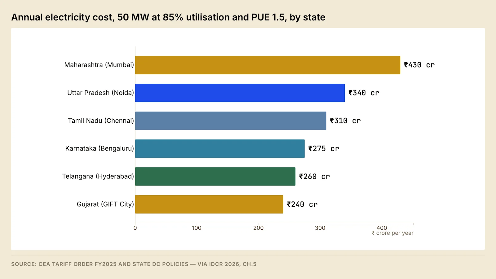
The differential between the most and least expensive major markets, measured on an identical load at identical utilisation, exceeds what any operational improvement can recover. A full point of PUE improvement on the same facility is worth a fraction of it. This is the arithmetic that explains why Hyderabad and Chennai have grown faster than Mumbai despite weaker submarine cable connectivity, and it is the arithmetic a Tier-2 location has to beat on grid access rather than on land price.
The tariff position is not permanent and should be diligenced rather than assumed. State data centre policies attach incentives to eligibility thresholds, and both the thresholds and the incentives are revised. Post 7 sets out how the landed cost is assembled and which components a developer can act on.
7.1 The determination of a state retail tariff #
A distribution licensee's tariff is determined by the State Commission on a petition setting out the annual revenue requirement, which comprises power purchase cost, transmission and distribution charges, operation and maintenance, depreciation, interest and a return on equity, less non-tariff income.
Differences between states arise in three places: the cost of the licensee's contracted generation, the level of distribution loss, and the extent to which industrial and commercial categories carry the subsidy for agricultural and domestic categories. All three change slowly, which is the mechanism behind the stability of the differential in figure 1.
The screening failure is to read the current schedule without the trajectory behind it. A licensee carrying an accumulated revenue gap recovers it in later years from the categories able to bear it, and a large HT or EHV consumer is one of those categories.
The diligence question is to obtain the last three tariff orders for the applicable category together with the licensee's approved revenue gap. The differential governs supply taken from the licensee, and where an open access or captive structure is available the landed cost is assembled from a different set of components.
7.2 The legal status of an incentive #
Incentive value is contingent on the instrument that carries it, and instruments of very different standing are routinely described by the same word.
Instrument | What it establishes | What it supports |
Announcement or press statement | Political intent | Nothing modellable |
Notified policy | The scheme, its conditions and its period | An application |
Order or guideline under the policy | Sanctioning authority, disbursement route | A budgeted claim |
Sanction letter to a named project | Quantum and attached conditions | A model input |
The rule that follows is to price legal status and implementation risk separately from incentive value, which is the position the India Data Centre Review 2026 reaches from its own register of state policy instruments.
8. Worked example #
Model assumption — weighted scoring for a 60 MW IT load build-to-suit, target energisation Q4 2028
Criterion | Weight | Navi Mumbai | Chennai OMR | Tier-2 inland node |
EHV headroom, firm under N-1 | 22% | 6 | 7 | 9 |
Corridor capacity and augmentation status | 16% | 6 | 6 | 8 |
Landed energy cost | 15% | 5 | 7 | 9 |
Water security under drought | 12% | 6 | 4 | 8 |
Fibre route diversity | 12% | 9 | 9 | 4 |
Latency to demand centres | 8% | 9 | 8 | 5 |
Land cost and title | 7% | 4 | 6 | 9 |
Policy and incentive value | 5% | 6 | 7 | 8 |
Operations talent availability | 3% | 9 | 8 | 4 |
Weighted score | 100% | 6.40 | 6.76 | 7.60 |
The Tier-2 node leads on headroom and landed energy cost and trails on fibre diversity and operations staffing. Navi Mumbai leads on connectivity and trails on every power-related criterion, which under a power-weighted scoring places it last of the three. A weighted score of this kind is a method for making trade-offs explicit rather than a decision rule, and the weights are deal-specific: shifting weight from the power criteria to latency and fibre reverses the ordering without changing a single raw score.
What resolves the comparison is the anchor tenant's workload mix, because it determines which weights apply. A training anchor raises the weight on power and lowers it on latency, which selects the Tier-2 node. An inference anchor does the reverse. Screening the anchor before the site is therefore the first action in the sequence, notwithstanding that it does not appear in the table in section 1.
8.1 Testing a weighted scorecard #
Three tests apply before a weighted score is used to support a decision.
Recompute the total from the weights and the raw scores. A scorecard revised across successive drafts frequently retains totals produced by a superseded weighting, and recomputation is the only way that discrepancy is found.
Separate the gates from the scores. Screens one to four carry disqualifying conditions, and a disqualifying condition cannot be compensated by a high score on another criterion, so scoring runs only over the sites that have passed the gates.
Re-run the ranking with the weight on the criterion that separates the candidates set to zero, then re-run it at double that weight. Where the ranking survives both, it is robust to the weighting. Where it does not, the decision is a judgement about weights rather than about sites, and it should be recorded as one.
8.2 Worked instance — corridor loading at a node with available headroom #
The first screen and the second return different answers at the same node more often than a shortlist suggests, and the arithmetic that separates them is short enough to run during screening. The instance below takes the firm requirement derived in section 2 and applies the contingency test described in section 3.1 to the pair of circuits feeding the substation that would serve it.
Model assumption — corridor test for a firm requirement of 159 MVA on two parallel feeding circuits
Step | Calculation | Result |
Thermal rating of each circuit | Stated at the design ambient temperature | 400 MVA |
Background flow on the corridor at system peak | Stated | 240 MVA |
Flow per circuit, both in service, before the new load | 240 ÷ 2 | 120 MVA |
Loading per circuit, both in service, before the new load | 120 ÷ 400 | 30% |
Loading of the surviving circuit, one out, before the new load | 240 ÷ 400 | 60% |
Corridor flow with the new load added | 240 + 159 | 399 MVA |
Loading per circuit, both in service, with the new load | 199.5 ÷ 400 | 50% |
Loading of the surviving circuit, one out, with the new load | 399 ÷ 400 | 100% |
Screening threshold applied in section 3 | Stated | 80% |
The connection sits comfortably inside the rating in the normal state and outside it under the contingency, and the two results differ by a factor of two because the loss of one circuit transfers its entire flow to the other. A screening exercise reading the normal-state figure will carry this node onto a shortlist, and the utility's study will return a strengthening condition whose cost and programme are then attributed to the incoming load under the mechanism examined in Post 3.
The instance also shows why the ambient assumption behind the rating has to be recovered. The rating in the first row is stated at a design ambient temperature, and the Indian system peak arrives at the least favourable cooling condition of the year, so a rating quoted against a milder ambient returns a loading percentage that is optimistic at precisely the hour the test exists to cover.
No action available to the developer changes the redistribution once a circuit is lost, so the remedies are limited to two. The first is to look for a node where the same requirement lands on a corridor carrying more circuits or more spare capacity. The second is to offer a curtailable fraction of the load against the contingency, which converts a firm requirement into a smaller firm requirement with a flexible remainder, and the terms on which that is done are set out in Post 10.
8.3 Worked instance — a scored cell taken to a site file #
A screening surface of the kind described in section 3.3 produces cells, and a cell is not a site. The instance below follows one published cell through the conversion.
Attribute of the cell | Value |
Cell | Angargan |
Demand score | 78.7 |
Grid access score | 60.4 |
Nearest mapped substation | Balugaon |
Distance to that substation | 14.7 km |
Source: EnergyMap Odisha Evidence Lab, via IDCR 2026, Chapter 5.
The divergence between the two scores is the signal the surface exists to produce. A cell scoring well on demand and less well on access is a cell where the demand case is established and the network case is not, which is an instruction about where to spend investigation rather than a conclusion about the site.
The distance in the fourth row converts the ranking into a cost and a programme. A cell whose nearest mapped asset lies at that distance requires a dedicated line over the intervening ground, so the line rather than the substation governs the schedule, and the right of way for it becomes the binding activity. The statutory position on right of way is set out in Post 3, and it is the point at which a developer without a distribution licence discovers that it holds no power to place a line across land it does not own.
Quantity the ranking leaves open | Artefact that settles it | Screen |
Firm capacity at the identified substation under N-1 | Capacity response from the STU or licensee | 1 |
Post-contingency loading of the circuits feeding it | Load flow extract, or the transmission plan entry | 2 |
Physical route diversity into the cell | Chainage-referenced route records from each provider | 3 |
Assured non-potable supply in a dry year | Municipal allocation letter, with the groundwater record | 4 |
Marketable title over a contiguous parcel inside the cell | Title chain and encumbrance record | 5 |
The ordering of that table is the screening sequence, and the cost of the work rises down the rows. A cell that fails the first row is abandoned before any of the remaining artefacts is commissioned, which is the saving the sequence exists to produce.
9. Land, ground conditions and the approval inventory #
The land screen sits fifth in the sequence because a parcel bought badly can be written down, and the four screens above it cannot be recovered from at any price. It is nevertheless the screen carrying the largest number of artefacts and the longest verification interval in the table in section 1, and the scorecard in section 8 compresses the whole of it into a single criterion. This section sets out what that criterion contains, together with the policy screen that follows it.
The organising distinction is between the site-dependent and the project-dependent. An investigation or an approval returning the same answer whichever parcel is chosen carries no information for a screening exercise, however important it remains to the project. One whose answer changes with the parcel belongs inside the screen and has to be run before the parcel is committed.
9.1 Land aggregation and the title chain #
Campus parcels in India are usually assembled rather than bought, because contiguous holdings of the required size in the required location are rare outside allotted industrial estates. Assembly changes the character of the title risk in three ways.
The first is concentration. The exposure runs to the weakest transaction in the set rather than to the average of them, because a block assembled from many holdings carries as many title chains and a defect in any one of them sits inside the campus boundary rather than beside it.
The second change is geometric. A holding in the interior of the assembled block that cannot be acquired renders the layout unbuildable even where the total area has been reached, because the receiving substation, the heavy-plant access route and the incoming line corridor each have to be placed somewhere and their positions are constrained by the connection rather than by the building. A gap at the edge can be absorbed by moving the boundary, and a gap in the interior cannot.
The third is price. The cost of the last holdings is a function of how visible the assembly has become, so the order in which owners are approached is a commercial decision rather than an administrative one, and the approach to the parcel carrying the substation should not be the one that reveals the scheme.
Title is established from the record rather than from occupation. The revenue record names the recorded holder and the mutation entries by which the holding reached them. The encumbrance record maintained by the registering authority lists the registered transactions affecting the property over a stated period and a stated jurisdiction. The search runs back far enough to cover the period within which a competing claim could still be brought under the Limitation Act, 1963, and an opinion that does not state its search period has not stated what it examined.
Defect | How it presents | Effect on the project |
Unregistered agreement to sell held by a third party | Absent from the encumbrance record entirely | A claim to enforce the agreement against the parcel |
Succession or co-parcenary interest not joined | A seller conveying more than the share held | A co-owner outside the transaction |
Interest of a minor conveyed without permission | Visible in the family's earlier documents | A transaction the minor may later avoid |
Tenancy or occupancy right in the revenue record | An entry naming someone other than the holder | Statutory protection for the occupant |
Purchaser not qualified to hold agricultural land | Raised at the point of registration | The conveyance cannot complete as structured |
Parcel inside a Scheduled Area | The area classification in the revenue record | Transfer to a non-tribal purchaser restricted |
Pending litigation over the parcel | A suit affecting the property | A purchaser bound by the outcome |
Acquisition notification over part of the block | A notification predating the purchase | Part of the block lost to the layout |
Access parcel in separate ownership | No recorded access from a public road | No legal means of entry to the site |
Four instruments govern the transaction. The conveyance operates under the Transfer of Property Act, 1882. Registration under the Registration Act, 1908 is what makes it effective against third parties and places it in the record a later purchaser will search. Duty is assessed under the applicable stamp legislation, and an instrument that has not borne the correct duty is at risk when it is relied on. The Limitation Act, 1963 fixes the period within which a competing claim can be brought and therefore the period a search has to cover.
Where the parcel is an allotment inside a state industrial estate the risk set changes rather than disappears. The interest is commonly leasehold rather than freehold. The allotment carries a permitted use and a period within which development has to be completed, and failure to develop can attract resumption. Transfer of the allotment requires the allotting body's consent, and a change in the control of the allottee can require consent in its own right, which interacts with a later sale of the company rather than of the land. That interaction is treated in Post 12.
The failure mode is a title opinion delivered on the seller's documents alone, without a boundary survey against the revenue map, because boundaries recorded in revenue maps are not survey-accurate and the area conveyed can differ from the area occupied. The diligence questions are the search period covered by the opinion, the jurisdiction and period of the encumbrance certificate, whether physical possession matches the record, and whether a boundary survey has been carried out. The same documents are examined again at exit, and the set a buyer will call for is listed in Post 12.
9.2 Zoning, permitted use and conversion #
Permitted use is fixed by the development plan prepared for the area by the planning authority, and a data centre's permissibility turns both on the use zone and on the definition the state applies to the activity. Some states treat it as an industrial use and others as an information technology use with its own entitlement, and the classification determines the built area permitted, the parking required and the fee payable. The classification is a state variable that moves with a policy revision, so it is verified against the current instrument rather than against what was permitted at a neighbouring campus.
Agricultural land requires a separate order converting it to non-agricultural use, issued by the revenue authority with a fee and with conditions attached. The order is site-dependent and sits upstream of the building plan approval, which places it early in the approval programme rather than in the middle of it.
Parameter in the development control regulations | Effect on a campus layout |
Floor area entitlement | Total built area, and the number of halls the parcel supports |
Ground coverage | Competition between built area and the plant yard |
Setbacks | Position of the receiving substation and the fire tender path |
Height limit | Rarely binding, except on a parcel near an aerodrome |
Parking provision | Land consumed by an activity with a small headcount |
Ground coverage and setbacks bind more often than height, because the plan form of a campus is driven by the switchyard, the generator yard, the heat rejection plant and the fire tender circulation rather than by the halls themselves.
The failure mode is a parcel purchased against an expected revision of the development plan. A revision under preparation is an intention until it is notified, and its standing is the standing of an unnotified incentive as set out in section 7.2. The diligence questions are the sanctioned plan extract with its date, the zone in which the parcel falls, the entitlement applying to the intended use, and whether any change of zone is pending.
9.3 The geotechnical investigation and foundation cost #
A geotechnical investigation answers two questions: what the ground will carry, and how much it will move under load. Both are answered from boreholes on a grid whose spacing follows from the footprint and from the variability the first holes reveal, with penetration testing at intervals, undisturbed sampling for laboratory classification and strength, and a record of the groundwater level together with its seasonal movement. The method is governed by the Bureau of Indian Standards code of practice for subsurface investigation for foundations, IS 1892.
The output is a safe bearing pressure at a stated depth with a settlement estimate against it, and from those a recommendation between a shallow foundation and a piled one. The cost consequence follows from the depth at which competent material is found rather than from the area of the parcel, because the quantity that varies between sites is the length of foundation needed to reach that depth.
Ground condition | Consequence for the foundation | Stage at which it appears |
Made ground or old quarry fill | Deeper foundations, or improvement across the footprint | Borehole logs |
Expansive clay | Under-reamed piles or a stiffened raft, against seasonal movement | Laboratory classification |
High water table | Dewatering during construction, uplift design for trenches | Water level record, if taken in the wet season |
Soft marine clay | Long-term settlement, and differential movement along a hall | Consolidation testing |
Shallow rock | Good bearing, expensive trenching and expensive piling | Refusal depth in the boreholes |
Aggressive soil or groundwater chemistry | Concrete specification and protection to buried metalwork | Chemical suite on soil and water samples |
Two features of a data centre make the foundation more sensitive than the built area suggests. Floor loading is high and concentrated, because battery rooms, switchgear and transformer plinths impose point loads well above those of an office use over the same area. Tolerance for differential movement is low, because a long hall carrying containment, busway and piped cooling is intolerant of relative settlement between bays. Seismic design follows from the zone in which the site falls under the Indian standard criteria for earthquake resistant design of structures, IS 1893, and it governs the anchorage of heavy plant as much as it governs the frame.
A piled solution is a programme item as well as a cost item, because rigs, integrity testing and load testing add duration at a stage of the works that sits ahead of everything else on the site. Where the investigation is commissioned after the parcel is committed, its finding cannot change the site and can only change the budget. The line of the capital cost composition in which the investigation itself sits is set out in Post 1.
The failure modes are consistent across markets. The investigation covers the hall footprint and not the switchyard, so the plinths carrying the heaviest single items on the site are designed on interpolated data. The investigation is carried out in the dry season, so the recorded water table understates the design condition. The chemical suite is omitted, so the concrete specification is settled without it. The diligence questions are the number and depth of holes against the footprint, the season in which the water level was recorded, and whether the switchyard and generator yard were investigated as well as the halls.
9.4 Flood return period and the platform level #
A flood level is a level with an annual probability of being exceeded, and the return period quoted against it is the reciprocal of that probability. The level is estimated by fitting a distribution to the annual maxima in a gauged record, so a long return period estimated from a short record is an extrapolation beyond the observed range rather than a reading from within it, and the confidence attaching to it is correspondingly weak. The fit also assumes the record is stationary, which is the assumption most exposed to a catchment that has been developed and to a rainfall regime that is changing.
Two distinct floods have to be assessed, and they are estimated by different methods. Fluvial and coastal flooding is estimated from gauged records held by the national and state water resources agencies. Pluvial flooding arises where the local drainage system is overwhelmed by rainfall falling on the site and its surroundings, it does not appear in a river gauge, and it is the mechanism behind most Indian urban flooding. A site can sit above every mapped river level and still take water from a drain that surcharges into it.
Level | What it protects | Note |
Finished floor level of the halls | The IT load and its distribution | Set above the design flood level with a freeboard |
Platform level of the switchyard | The connection itself | Frequently the lowest built level on the site |
Plinth level of generators and fuel storage | The backup supply | Losing it removes the response to the flood |
Invert of cable trenches and duct entries | Every cable entering the site | The path most often overlooked |
Level of the site access road | Staff access and fuel resupply | Determines whether the site can be reached |
The site's own development alters the assessment it was tested against. Replacing a permeable surface with hardstanding raises the runoff leaving the parcel and shortens the time it takes to arrive, so the discharge reaching the drainage system is not the discharge that system was sized for. The consent to discharge surface water into the receiving system is therefore a site-dependent approval with a design consequence rather than an administrative formality.
Raising a platform is the standard remedy and it carries three consequences. Imported fill has to be placed and compacted in layers, which is a programme item. It settles under its own weight and under the load placed on it, which is a design item interacting with section 9.3. It has to be won from somewhere and hauled, which is a cost item sensitive to the availability of material near the site.
The failure modes are levelling the site to the adjoining road because the road is the visible datum; carrying a cable trench below platform level while the buildings sit above it; adopting a river gauge some distance away because it is the nearest published record; and relying on an assessment that predates a development upstream which changed the catchment. The diligence questions are the datum against which the level is quoted, the return period, the source and length of the record, and the date of the assessment.
9.5 Soil resistivity and the area taken by the earth grid #
At the screening stage, soil resistivity is a land quantity. The earth grid serving the receiving substation occupies area inside the site boundary, and how much area it occupies depends on the resistivity of the ground beneath it and on the current it has to pass into that ground.
Resistivity is measured with a four-electrode array at a series of electrode spacings, because the apparent resistivity recorded at each spacing samples a different depth, and the design proceeds against a layered model of the ground rather than against a single value. A survey run at one spacing produces a number that cannot be used, since it cannot distinguish a thin conductive surface layer over resistive rock from uniform ground of intermediate resistivity.
The current the grid has to pass is a fraction of the fault current available at the site, so the earthing design cannot be closed until the fault level discussed in section 2.7 is settled. The two site questions are coupled, and a site combining high resistivity with a high fault level consumes the most land of any combination, because the grid has to spread a larger current through more resistive ground while holding step and touch potentials inside their limits.
Site condition | Consequence for the earthing installation |
High resistivity, typical of hard rock terrain | Larger grid area, deeper electrodes, or ground enhancement material |
Low resistivity with high salinity, typical of coastal ground | Smaller grid, and a corrosion exposure for buried conductors and joints |
Strongly layered ground | Design against a layered model; a single measured value misleads |
High fault level at the point of supply | More grid current, and more area for the same potential limits |
Each remedy for high resistivity is either land or a recurring obligation. Area and depth consume the parcel, and chemical enhancement of the ground has to be maintained over the life of the installation. Where the parcel is constrained, the area taken by the grid competes directly with the switchyard area discussed in section 2.5, which is a further reason for settling the electrical land requirement before the parcel is committed.
The functions the earthing system performs, and the way each is verified in the completed installation, are set out in Post 4. Design practice follows the Indian code of practice for earthing, IS 3043. Substation grounding practice is set out in the guide published as IEEE Std 80.
The diligence questions are the electrode spacings used in the survey and the season in which it was run, whether the survey covered the switchyard location rather than only the building footprint, and whether the soil chemistry from the geotechnical investigation has been read against the conductor material proposed.
9.6 The approval inventory and the critical path #
A campus requires approvals from several authorities, and a screening exercise is interested in the subset whose answer changes with the parcel. The remainder still has to be obtained, and it belongs to the programme rather than to the screen.
Approval | Issuing authority | What it gates | Answer changes with the parcel |
Conversion to non-agricultural use | Revenue authority | Building plan approval | Yes |
Building plan and layout approval | Local body or development authority | Start of construction | Yes |
Prior environmental clearance, where the applicable threshold is crossed | The appraisal authority named in the notification | Consent to establish | Yes |
Consent to establish | State Pollution Control Board | Construction, and the later consent to operate | Yes |
Consent to operate | State Pollution Control Board | Commercial operation | No |
Fire and life safety approval | State fire service | Occupancy | No |
Petroleum storage licence | The explosives authority | Fuel filling, and integrated systems testing | Partly |
Electrical inspectorate approval | State electrical inspectorate | Energisation | No |
Groundwater abstraction permission | The competent groundwater authority | Use of an on-site source | Yes |
Height clearance near an aerodrome | The airport authority | Building plan approval | Yes |
Way-leave for ducts in the public road | Road authority or municipal body | Fibre entry and the incoming cable | Yes |
Tree felling permission | Forest or municipal authority | Site clearance | Yes |
Consent to discharge surface water | The receiving drainage authority | Site drainage design | Yes |
The pollution control approvals rest on the Water (Prevention and Control of Pollution) Act, 1974 and the Air (Prevention and Control of Pollution) Act, 1981. The environmental clearance regime operates under the Environment (Protection) Act, 1986 and the impact assessment notification issued under it, and whether a particular campus is caught by it depends on the built area threshold in the notification as it stands at the time of application. Fire and life safety compliance follows the National Building Code of India. The petroleum storage licence and the instruments binding a generator installation are treated in Post 6.
An approval sits on the critical path where an activity cannot begin without it and no float separates the two. Four of the rows above satisfy that condition on most campuses, for different reasons.
Building plan approval gates the start of construction, so delay in it is transmitted into the programme at full value with nothing to absorb it.
Consent to establish also gates construction, and where an environmental clearance is required it gates the consent, so the pair runs in series. Both have to be started against the earliest date at which the design is defined well enough to support an application, which is earlier than most programmes assume.
Electrical inspectorate approval gates energisation, so it sits at the end of a long chain, and delay in it presents as a connection delay with no physical cause. The dependency is set out in Post 3.
The petroleum storage licence gates fuel filling, which gates integrated systems testing, which gates handover, so an approval that reads as administrative sits immediately upstream of commercial operation.
The characteristic failure is an approval granted subject to a condition discovered late. A monitoring installation, a discharge limit, a green belt obligation or a restriction on construction hours arrives after the design is fixed, and the cost of accommodating it is at its highest at that point. The diligence question is therefore for the conditions attached to comparable approvals in the same jurisdiction rather than for the fact of the approval, and a developer with no comparable project in that state has to obtain them from an adviser who does.
9.7 Operations staffing and site access #
The seventh screen is the cheapest to run and the one most often deferred. What it tests is the depth of a local pool capable of sustaining a continuous shift roster at the required competency, together with the reachability of the site at shift change, rather than a headcount.
Quantity | Why it varies with the parcel |
Travel time at shift change | Determines whether a roster can be staffed from the local pool at all |
Response time of a specialist maintenance contractor | Sets the restoration time after a plant failure |
Distance to a recruitment and training catchment | Determines the cost of building a pool where none exists |
The interaction with the resilience class runs in one direction. A facility whose topology tolerates a longer repair carries a weaker requirement on contractor response time, and a facility built to a lower redundancy class needs the contractor closer to it. The composition of the shift establishment and the competencies it has to carry are set out in Post 9.
Forward look #
Three developments would alter the screening sequence over the next eighteen months.
The first is the revived National Data Centre Policy at MeitY. If the proposed Data Centre Economic Zones with pre-provisioned power and single-window clearance are notified, screening effort inside those zones shifts from network discovery to zone selection, and the first two screens become substantially cheaper to satisfy.
The second is the extension of the distribution licence route beyond the states that have granted it. Where a developer can hold a licence, the distribution licensee ceases to be a gatekeeper and becomes a counterparty, which changes both the connection process and the tariff position. Andhra Pradesh has granted one and published a framework for further applications, and the states with the longest connection queues face the most difficult decision on whether to follow.
The third is rack density. If leasing at high densities becomes the norm, the MVA requirement per acre rises sharply and a number of currently attractive parcels become undersized for the connection they would need, without any change in their physical characteristics.
FAQ #
In what order should Indian data centre sites be screened? Extra-high-voltage substation headroom, upstream corridor capacity, fibre and latency, water under drought conditions, land, policy incentives, then operations staffing. The order reflects irreversibility rather than cost, because the early screens can terminate a project and the later ones cannot.
How much grid connection does a data centre need? The requirement is derived from IT load through power usage effectiveness, house load and power factor, and must then be available as firm capacity under an N-1 contingency. Section 2 sets out the derivation step by step.
Why is installed substation capacity not the right screening figure? Installed capacity is the sum of all transformers. Firm capacity is what remains with the largest element out of service, and existing committed load must be deducted from it. A substation can carry an installed nameplate several times the available firm headroom.
Does proximity to a substation indicate available capacity? No. Proximity and voltage class identify the network counterparty to approach. Bay availability, transformation capacity and upstream reinforcement obligations require documentary evidence from the utility.
Why does the tenant's market affect site selection? It determines when the facility draws its peak load. A facility serving European hours peaks during the Indian evening peak; one serving North American hours peaks overnight. This affects the tariff, the deviation settlement exposure, and the distribution licensee's disposition toward the connection.
Which approvals sit on the critical path for an Indian data centre campus? Building plan approval gates the start of construction. Consent to establish gates construction as well, and is itself gated by an environmental clearance where the project crosses the applicable threshold. Electrical inspectorate approval gates energisation. The petroleum storage licence gates fuel filling and therefore integrated systems testing. Section 9.6 sets out the full inventory and identifies which approvals change their answer with the parcel.
Sources #
Savills India, India Data Centre Market Update H1 2026, July 2026
ResearchAndMarkets, India Existing and Upcoming Data Center Portfolio, April 2026
Mordor Intelligence, India Data Center Market Report, June 2026
CEA, Technical Standards for Connectivity to the Grid Regulations
Vercellino et al., measured GenAI workload power traces, arXiv:2604.07345, April 2026
India Data Centre Review 2026 (v2.3, edition cutoff 28 July 2026), Chapters 5 and 8 — India Energy Atlas
CGWB, Dynamic Ground Water Resources 2023, via IDCR 2026
S&P Global Sustainable1, water stress assessment 2025, via IDCR 2026
CEA, tariff order FY2025 and state data centre policies, via IDCR 2026
Loudoun County data centre brief, substation connection queue, via IDCR 2026
EnergyMap substation coverage and Odisha Evidence Lab demand-score cell, 13 July 2026, via IDCR 2026, Chapter 5
Transfer of Property Act 1882; Registration Act 1908; Limitation Act 1963; Water (Prevention and Control of Pollution) Act 1974; Air (Prevention and Control of Pollution) Act 1981; Environment (Protection) Act 1986 and the impact assessment notification issued under it — named at instrument level only
IEC 60076 series, loading guide for oil-immersed power transformers; IS 1892, subsurface investigation for foundations; IS 1893, criteria for earthquake resistant design; IS 3043, code of practice for earthing; IEEE Std 80, substation grounding; National Building Code of India — named at instrument level only, with no clause or limit value taken from any of them
The connection derivation and its power usage effectiveness sensitivity, the transformer load-sharing and unit-count tables, the corridor loading instance, the sanctioned demand comparison, the weighted scorecard and the load-profile analysis are modelled by India Energy Atlas and are labelled as model assumptions. IDCR 2026 figures are quoted at the locked edition snapshot of 13 July 2026; live Atlas products may carry newer records.
This post was revised against the measured GenAI load-profile analysis — see the working note for the load derivation, ramp rates and the peak-to-nameplate ceiling.
Read the full series — The Indian Data Centre Playbook, twelve parts from unit economics to exit.
Next in the series — Part 3: Securing the Connection. The regulatory path from connection application to energisation, and where the programme fails.
India Energy Atlas maps substation headroom, transmission corridors, and interconnection queues across India. See energymap.in/pricing.
Sources & method
- Savills India, India Data Centre Market Update H1 2026, July 2026 - ResearchAndMarkets, India Existing and Upcoming Data Center Portfolio, April 2026 - Mordor Intelligence, India Data Center Market Report, June 2026 - CEA, Technical Standards for Connectivity to the Grid Regulations - Vercellino et al., measured GenAI workload power traces, arXiv:2604.07345, April 2026 - India Data Centre Review 2026 (v2.3, edition cutoff 28 July 2026), Chapters 5 and 8 — India Energy Atlas - CGWB, Dynamic Ground Water Resources 2023, via IDCR 2026 - S&P Global Sustainable1, water stress assessment 2025, via IDCR 2026 - CEA, tariff order FY2025 and state data centre policies, via IDCR 2026 - Loudoun County data centre brief, substation connection queue, via IDCR 2026 - EnergyMap substation coverage and Odisha Evidence Lab demand-score cell, 13 July 2026, via IDCR 2026, Chapter 5 - Transfer of Property Act 1882; Registration Act 1908; Limitation Act 1963; Water (Prevention and Control of Pollution) Act 1974; Air (Prevention and Control of Pollution) Act 1981; Environment (Protection) Act 1986 and the impact assessment notification issued under it — named at instrument level only - IEC 60076 series, loading guide for oil-immersed power transformers; IS 1892, subsurface investigation for foundations; IS 1893, criteria for earthquake resistant design; IS 3043, code of practice for earthing; IEEE Std 80, substation grounding; National Building Code of India — named at instrument level only, with no clause or limit value taken from any of them The connection derivation and its power usage effectiveness sensitivity, the transformer load-sharing and unit-count tables, the corridor loading instance, the sanctioned demand comparison, the weighted scorecard and the load-profile analysis are modelled by India Energy Atlas and are labelled as model assumptions. IDCR 2026 figures are quoted at the locked edition snapshot of 13 July 2026; live Atlas products may carry newer records. Photography: - Photo by Amirreza Taqavi on Unsplash (https://unsplash.com/photos/electricity-pylon-and-power-lines-over-a-distant-cityscape-3jE_CJHhsmA?utm_source=india_energy_atlas&utm_medium=referral) - Photo by Fahim Junaid on Unsplash (https://unsplash.com/photos/a-large-blue-box-sitting-on-the-side-of-a-road-7MjXpkxFseU?utm_source=india_energy_atlas&utm_medium=referral)